The Most Overlooked Parameter Settings in PowerFlex Drives
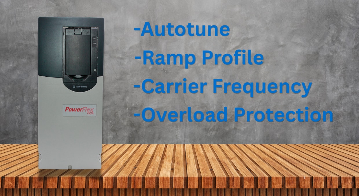
Teams with short timeframes set up Rockwell’s PowerFlex drives every day, and most of that work only touches the handful of parameters needed to make a motor spin: voltage, frequency, and a start reference. Once the motor turns, the commissioning checklist gets signed off, and everyone moves on to the next job. But PowerFlex drives feature dozens of secondary parameters that regulate efficiency, thermal load, fault tolerance, and lifespan. When these are left at their defaults and never reviewed, the drive still runs, but often well below its capabilities.
Neglected PowerFlex Parameters
Factory settings on a PowerFlex drive exist for one reason: broad compatibility. They are built to work across a wide range of motors and applications, which means they are rarely ideal for any single fixed installation. A default acceleration ramp, carrier frequency, or stall timer is enough to get a drive running. Still, it won’t match the thermal properties of a specific motor, the inertia of a specific load, or the electrical noise environment of a specific plant. The result is nuisance trips, premature bearing failure, and communication faults that trace back not to faulty equipment, but to default settings nobody reviewed.
Motor Control Tuning Parameters
Motor control tuning determines how quickly the drive can respond to the connected motor and load. While basic settings are enough to get the motor running, fine-tuning the VFD will allow the operator to get the most out of their equipment.
Nameplate Data and Autotune
Entering accurate motor nameplate data and running an autotune is the single most consequential step in configuring a PowerFlex drive. Rated voltage, current, frequency, and RPM all feed directly into the drive’s slip compensation and vector control algorithms. When technicians rush through nameplate entry or skip autotune altogether, the drive’s internal motor model is inaccurate, and torque production suffers, especially at low speed. On PowerFlex drives capable of sensorless vector or flux-vector control, skipping autotune wastes the very capability for which the drive was purchased, leaving it to perform more like a basic volts-per-hertz drive at flux-vector cost.
Static autotune measures stator resistance without spinning the motor. A rotate tune, available on many PowerFlex platforms, measures inductance and other dynamic properties for noticeably better control, but it requires the motor to be uncoupled from its load, a step technicians may overlook as disconnection takes time. The result is that many drives operating in flux vector mode rely on an incomplete static motor model, which limits torque accuracy in applications such as cranes or conveyors with variable loading, where accurate torque control matters most.
PWM Carrier Frequency
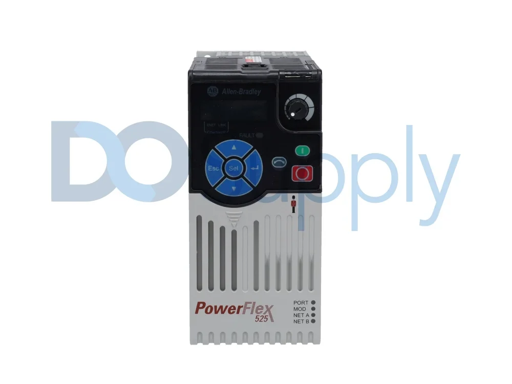
Carrier frequency, often defaulted to 4 kHz on many PowerFlex drives, is another setting left untouched far too often. Raising it reduces audible motor noise but increases switching losses in the drive’s IGBTs, which increases heat and can trigger an automatic current derate. Lowering it reduces switching stress and heat, letting the drive run cooler and closer to full capacity, but tends to bring back the audible motor whine and, on longer cable runs, can raise common-mode bearing current concerns. Engineers who never revisit this parameter either accept unnecessary derating on marginally sized drives or leave in noise that a better-matched setting would have eliminated. The right value depends on cable length, motor type, and ambient temperature, none of which a factory default accounts for. Motor manufacturers often publish a recommended carrier frequency range tied to winding insulation class, and checking that spec against the drive’s default is a five-minute task most commissioning schedules skip entirely.
Acceleration, Deceleration, and Ramp Profiles
Accel and decel times are usually set once during a rushed startup and never touched again. A ramp that’s too short for the connected inertia pushes the drive into current limit on acceleration or trips an overvoltage fault on deceleration, since regenerated energy has nowhere to go. An unnecessarily long ramp stretches out cycle times and wastes energy where a faster transition would do no harm. S-curve parameters, which round off the start and end of a ramp instead of applying a straight linear rate, are especially underused. Enabling an S-curve reduces mechanical shock on couplings, belts, and gearboxes during frequent starts and stops, extending component life. Yet, it sits disabled by default on most installations because nobody flags it until a coupling fails.
Protection and Fault Handling Settings
Protection parameters and fault handling settings determine how a drive responds when operating conditions move outside their normal range.
Stall and Overload Protection
Every PowerFlex drive includes stall detection and motor overload protection to prevent damage when a motor can’t reach commanded speed. These are frequently left at default thresholds that don’t reflect the connected load’s actual duty cycle. A drive running a large fan or a positive-displacement pump may need a longer stall timeout than the default, while a drive on a smaller motor may need a tighter current threshold than the default. Bus regulation settings further complicate this: when active on a high-inertia load, a drive can remain in a current-limited, decelerating state long enough to trip a stall fault, even when nothing is mechanically wrong. Engineers unfamiliar with this interaction often spend hours chasing a phantom overload before realizing the fix is a stall timer or bus regulation setting, not the motor.
Power Loss and Ride-Through Behavior
Ride-through parameters govern how a PowerFlex drive responds to a momentary loss of input power. At default, most drives will trip on even a brief voltage sag, which is fine for some applications but disruptive for continuous processes where a short dip shouldn’t stop production. For applications with a decent coasting load, such as a fan, ride-through mode can be configured to use the load’s own regenerated inertia to keep drive-control power alive through the interruption, avoiding a full restart. This setting is easy to overlook during commissioning because the power-quality issue that would expose the problem may not appear until months later.
Communication and Network Parameters
As more PowerFlex drives connect to EtherNet/IP, DeviceNet, or PROFIBUS networks, communication loss behavior ceases to be a networking detail and becomes a safety and process parameter. Many drives are left on their default fault response when comm is lost, without evaluating whether that response is actually safe for the process. On a conveyor synchronized with upstream and downstream equipment, an uncontrolled fault, such as comm loss, can cause more downtime than a controlled, orderly stop would. The same applies to IP addressing, communication timeouts, and drive-to-PLC data mapping, which are usually treated as one-time setup tasks instead of settings worth revisiting as network traffic and topology change over time.
Conclusion
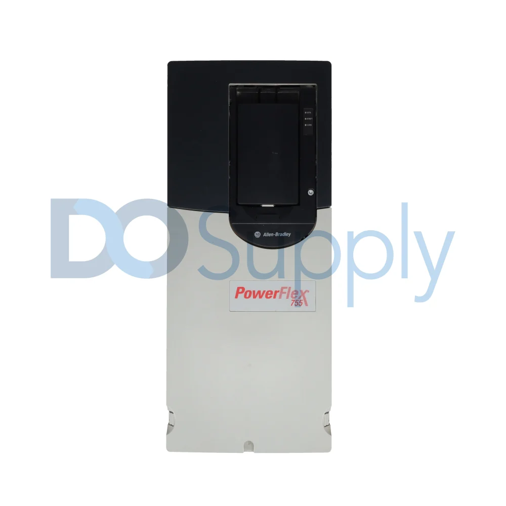
The parameters covered here rarely appear on a basic startup checklist, yet they determine whether a PowerFlex drive merely runs or actually performs reliably under real operating conditions. Motor tuning accuracy, carrier frequency, ramp profiles, stall and ride-through behavior, and communication fault handling all interact with each other and with the connected mechanical load in ways default values can’t anticipate. Engineers who take the time to evaluate these settings during commissioning, rather than during troubleshooting after a failure, get measurably better performance, fewer nuisance trips, and longer service life from the same PowerFlex hardware. Treating parameter configuration as an engineering task rather than a checklist item is what separates a drive that simply works from one that’s genuinely optimized for its application. Still, there may be some underlying issues that can cause motor heating other than incorrect parameters. If you would like to learn more, visit our blog post here.
If you find that your PowerFlex drive may have been impacted by improperly programmed settings or is faulting when it shouldn’t, schedule a repair time with us at DO Supply, and our technicians will fix your drive to get your motor control application back on track. We also stock a wide selection of PowerFlex drives and accessories for those seeking superior motor control. Give us a call today and let us help you find the right drive for your system.
DO Supply Inc. makes no representations as to the completeness, validity, correctness, suitability, or accuracy of any information on this website and will not be liable for any delays, omissions, or errors in this information or any losses, injuries, or damages arising from its display or use. All the information on this website is provided on an "as-is" basis. It is the reader's responsibility to verify their own facts.