What Happens Inside a VFD During a Power Sag?
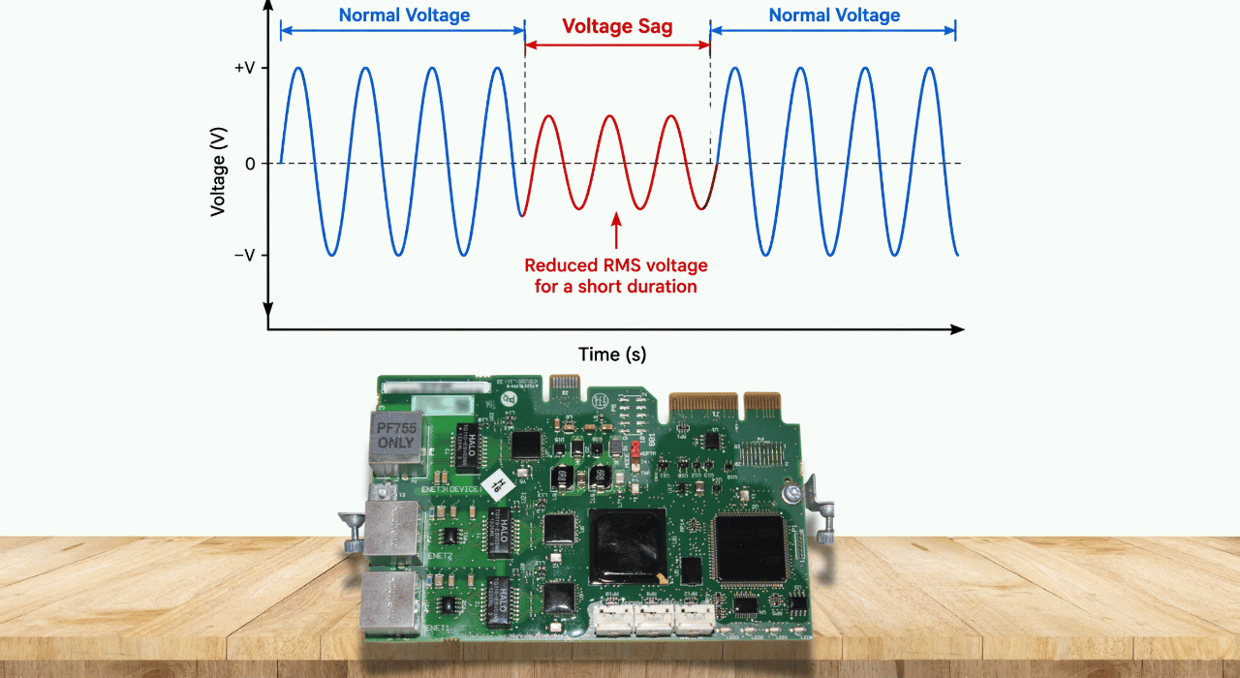
A voltage sag on the incoming AC line may seem like a minor issue with little effect on your drive, but this isn’t always true. Every frequency inverter has a DC bus that briefly absorbs fluctuations, deciding whether the sag causes a trip, an alarm, or lets the drive ride through the event. This article covers each part of that process, drawing on Schneider Electric’s insight into where the DC bus voltage comes from, and explains the internal chain from rectifier to DC bus and its protection, with examples of products offering this capability.
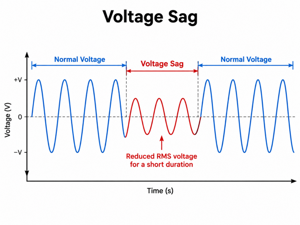
How the DC Bus Reacts to AC Voltage
A rectifier converts incoming three-phase AC to DC and charges the capacitors on the DC bus. For a typical diode-rectifier drive, the DC bus is roughly 1.35–1.41 times the RMS line voltage, depending on drive design and operating conditions. So where the input voltage is normally 480 V, the DC bus would read around 677 V. This lines up with figures quoted by Schneider Electric, who state that a 480V system has an average of 680 VDC. If 240 VAC were recorded instead, the DC bus would read about 340 VDC.
When the AC input voltage falls, the energy supplied through the rectifier also decreases. The DC-link voltage therefore begins to fall once the capacitors can no longer maintain their previous charge. This happens at the line, near the rectifier, where the VFD actually reads the voltage. The VFD’s fault log, however, records the DC bus voltage, not the line voltage. This makes it easier to spot issues when the line voltage starts to decline, since that decline shows up in what the DC bus records.
Why Doesn’t the VFD Drop Out Every Time Voltage Sags?
Even as the incoming power drops, the DC bus stays powered because the capacitors retain enough charge to keep it energized briefly. The motor may also keep running briefly, drawing on this last reserve of energy stored in the DC bus. How much energy is released from the DC bus, and how it behaves, is then measured and analyzed — different scenarios that cause the sag result in different power discharges.
If the drive’s undervoltage or kinetic ride-through function is enabled, the motor and load can provide a second energy buffer. The drive reduces motoring torque, allowing the system’s rotating inertia to regenerate energy back into the DC link as speed falls. This means not every disturbance has to be treated as a problem requiring a shutdown — a device at the front of the chain, such as the capacitor, means a constant voltage is not strictly required, and the bus will only sag as far as the situation actually demands.
Correcting Undervoltage Conditions
There are only a few standard ways to prevent trips, and they are broadly similar across manufacturers, as most VFDs are nearly identical, or at least very close, in how they handle this. ABB, which manufactures the ACS880, has built one of the simplest and most effective forms of this protection into the drive through the function 30.31 Undervoltage Control. When voltage decreases, this function works alongside the rest of the drive to try to prevent it from tripping.
Torque Reduction and Regenerating Support
The DC link voltage can gradually lower either because incoming AC power is cut off entirely or because the voltage is reduced. A full loss of AC power is the more immediate concern, since the VFD cannot reduce the torque it delivers to keep functioning, so it is normal for the drive to generate electricity on its own to stay powered. If it is simply a voltage sag rather than a full loss, engineers can more easily reduce the motor torque output in the VFD to keep the voltage within the normal range. That a VFD can ride through these disturbances on its own, generating enough electricity to sustain itself without triggering an alarm, is part of why manufacturers build drive lines such as the ACS880 with this level of resilience.
How the VFD’s Control System Detects and Decides
Detection and response logic sits at the control level, and Rockwell Automation’s PowerFlex 750 Series using TotalFORCE control is designed to handle both voltage sags and short-duration voltage losses. This involves detecting the voltage sag itself as well as detecting any loss of synchronization with the AC source.
When a disturbance is detected, the drive’s internal controls can be optionally set to adopt a specified response mode:
- Ignore – no corrective action
- Alarm – condition is flagged without affecting operation
- Ride Through – operation is maintained during the event
- Fault – the drive stops and registers a fault condition
The hardware does not determine the response to a sag; the power disturbance parameters do. Rockwell references immunity standards IEC 61000-4-11 and IEC 61000-4-34, which specify test methods for dips, interruptions, and voltage variations that industrial devices should withstand without impact on normal operation.
Undervoltage Thresholds for VFD Tripping
When a sag occurs:
- Power is maintained while the motor decelerates on the inertial or regenerative load
- Reduced output torque on the motor for a short period
When the input voltage recovers, torque output returns to normal once internal voltage levels are restored. Danfoss’s FC 301/302 documentation describes the alarm levels for a 380–500V drive in a sag context: a DC link voltage low warning (warning/alarm 6) occurs at 410 VDC, and a DC-side undervoltage alarm (warning/alarm 8) occurs at 373 VDC. Once the grid disturbance ends and the motor has slowed due to the sag, the inverter “speeds up” and manages recovery through parameter 14.10 (mains failure). Danfoss specifies that kinetic backup for undervoltage conditions must be enabled during a sag; the motor then runs in regenerative mode, generating voltage that helps maintain the supply. This is similar to the regenerative behavior of the ABB VFD described earlier. When a sag occurs, the DC bus voltage can be maintained through the motor’s rotational inertia and kinetic energy under undervoltage conditions, before the DC bus voltage collapses completely.
For a 380–500V drive, normal operation continues until the DC bus falls to 410 VDC, which triggers a warning, and 373 VDC, which triggers an alarm. These thresholds indicate progressively lower DC-link voltage conditions; they do not by themselves specify how much ride-through time remains.
Implementation Considerations
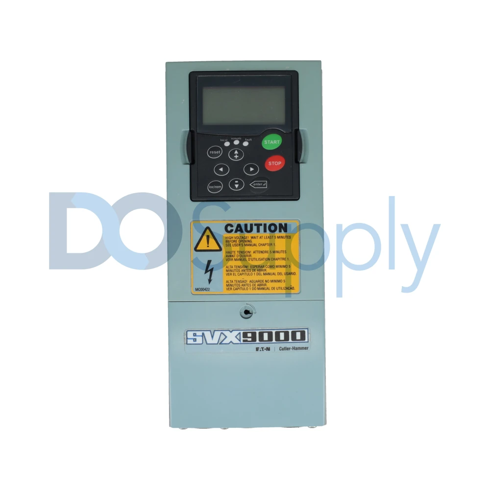
The ACS880 hardware specification describes how the drive implements voltage control through the 30.31 undervoltage control function, but doesn’t detail what happens to the contactor after an input power loss, or how long the drive can sustain itself. For example, if a sag causes the main contactor to drop out, the drive may not trip immediately, but its reliance on kinetic backup increases. Whether it eventually trips depends on the sag duration, the contactor drop-out time, and the 30.31 undervoltage control setting.
Fault code 3183, for example, is usually an undervoltage fault. When troubleshooting, check the grid-side contactor, the power-loss mode, and the undervoltage-level settings, as the contactor may be faulty even though the drive tends to get blamed.
Key Takeaways
A voltage sag doesn’t hit a VFD as a single, monolithic event — it triggers a chain reaction from the physical layer to the control layer. The sudden dip in AC voltage reflects on the DC bus as a proportional voltage drop; the large capacitors and rotational inertia act as buffers, but only temporarily; the undervoltage control function commands deceleration through motor braking; and the selected response mode determines whether a fault results. Fixed thresholds act as triggers that make this behavior comprehensible to service engineers — such as the 410V warning and 373V fault level on the Danfoss drive discussed above. Understanding this chain of events, from rectifier to DC bus to control function, is what makes voltage dip ride-through possible, rather than recurring, problem-producing shutdowns.
Power sags and undervoltage faults can be difficult to track down, as the problem may originate outside of the drive itself. Checking the DC bus, fault history, incoming power, and undervoltage settings can help determine whether the VFD, the power supply, or another system component is causing the issue.
At DO Supply, we carry replacement VFDs and related industrial automation equipment from manufacturers like Allen-Bradley, Johnson Controls, and Mitsubishi. We also offer repair services and a two-year warranty on all the items we sell and repair. If you need help replacing a failed drive or finding a compatible unit for an existing system, give us a call and our friendly sales team will point you in the right direction!
DO Supply Inc. makes no representations as to the completeness, validity, correctness, suitability, or accuracy of any information on this website and will not be liable for any delays, omissions, or errors in this information or any losses, injuries, or damages arising from its display or use. All the information on this website is provided on an "as-is" basis. It is the reader's responsibility to verify their own facts.