Understanding DC Bus Voltage in PowerFlex Drives
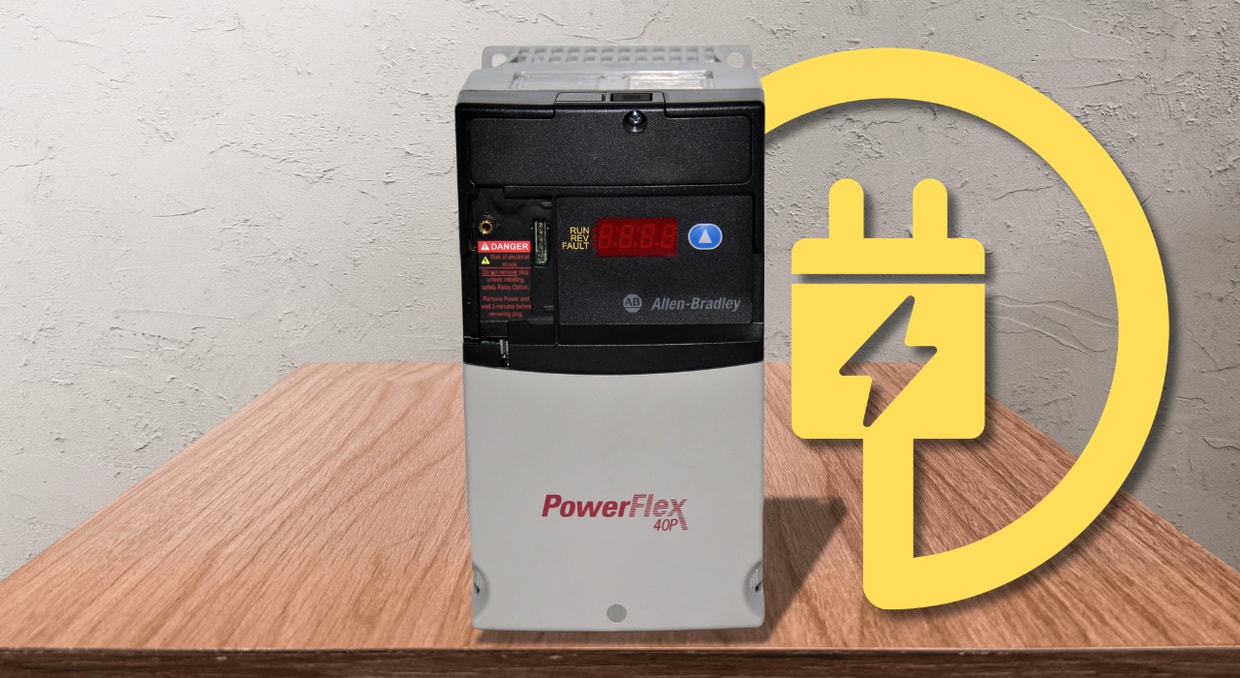
In PowerFlex variable-frequency drives (VFDs), the DC bus functions as the internal power bridge and electrical reservoir between the AC input rectifier and the output inverter stage. Once the incoming AC line voltage is rectified, the DC bus capacitors smooth and stabilize the resulting DC bus voltage by reducing voltage ripple, thereby delivering a steady DC supply to the inverter. They also temporarily absorb the regenerative energy produced during overhauling-load conditions or motor deceleration, reducing rapid voltage fluctuations and improving energy efficiency.
This article provides a comprehensive overview of the fundamentals of DC bus voltage in Allen-Bradley PowerFlex drives. Knowledge of pre-charge drive operation, DC bus capacitors, shared DC bus configurations, DC bus regulation, regenerative energy management, and common DC bus-related faults enables engineers and maintenance personnel to maximize the reliability of PowerFlex drives, improve overall system performance, and extend component life.
What is DC Bus Voltage?
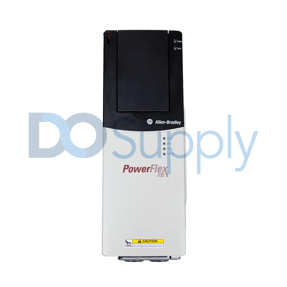
In PowerFlex AC drives, the incoming three-phase AC line voltage is first converted into DC voltage by the drive’s input rectifier stage. Standard Allen-Bradley PowerFlex drive models, such as the PowerFlex 753, use a passive six-pulse diode bridge in their rectifier section for this conversion. Specialized regenerative drive models, such as the PowerFlex 700AFE and PowerFlex 755TR, employ Active Front End (AFE) rectifiers that use an LCL filter and Insulated Gate Bipolar Transistors (IGBTs). For medium-voltage and heavy-duty industrial applications, certain PowerFlex drives, such as the PowerFlex 700/700H and PowerFlex 6000/7000 AC drives, use specialized multi-pulse passive rectifiers with multiple standard diodes or SCR (Silicon Controlled Rectifier) bridges.
The rectified DC voltage is then filtered and stored in a DC bus consisting primarily of a bank of large film or electrolytic capacitors and, in some drive configurations, inductive components. The DC bus capacitors smooth the rectified DC voltage, provide temporary energy storage, and supply a stable DC voltage to the inverter section. The inverter stage uses high-speed Insulated-Gate Bipolar Transistors (IGBTs) to convert the DC bus voltage into a pulse-width-modulated (PWM) signal with adjustable voltage and frequency to precisely control the connected AC motor.
In a nutshell, DC bus voltage is the intermediate direct-current (DC) voltage generated when the incoming 3-phase AC line voltage is rectified within a PowerFlex drive. This DC bus voltage is then filtered and stabilized by the DC bus capacitors. Under normal operating conditions, a standard 480V AC (RMS) input yields a nominal DC bus voltage of approximately 650V DC after rectification. Under heavy motor loads or transient conditions, this value may decrease slightly due to increased current drawn by the PowerFlex drive and input-voltage variations.
When the PowerFlex drive is operating with little to no applied load, the nominal DC bus voltage is approximately equal to the peak value of the rectified AC input voltage. In essence, the measured nominal DC bus voltage varies with the incoming AC supply voltage, line conditions, and operating state of the PowerFlex AC drive. Listed below are typical nominal DC bus voltage ratings for common AC line voltages:
- 240V AC input: 324V DC output
- 380/400V AC input: approximately 540V DC output
- 600V AC input: 810V DC output
- 690V AC input: approximately 932V DC output
The Role of DC Bus Capacitors
The DC bus capacitors in PowerFlex AC drives perform several critical functions. First, they filter the rectified AC line voltage to reduce voltage ripple and generate a smooth, stable DC bus voltage that is delivered to the inverter stage. They also provide a low-impedance energy source to meet the high-frequency switching demands of the IGBTs, helping minimize voltage fluctuations during inverter operation. Additionally, these capacitors act as an energy buffer, sustaining PowerFlex drive operation during transient voltage sags and brief power interruptions.
The required total DC bus capacitance depends directly on both the drive’s input voltage class and power rating. PowerFlex drives with high power ratings require larger DC bus capacitance to maintain a stable DC bus voltage during peak loading and periods of increased current demand. Over time, the electrolytic DC bus capacitors gradually deteriorate due to natural aging, resulting in a significant reduction in capacitance while their equivalent series resistance (ESR) increases. This degradation mechanism is one of the most common causes of hardware failure in legacy PowerFlex drives.
As the DC bus capacitors deteriorate, the resulting excessive DC bus ripple voltage places additional thermal and electrical stress on the IGBTs, accelerating their degradation. This reduces the overall reliability of PowerFlex drives and can trigger nuisance faults, including DC bus undervoltage and input phase loss faults.
PowerFlex drives provide specialized diagnostic parameters that help assess the health of the DC bus capacitors. For example, Parameter 3 (DC Bus Volts) reports the DC bus voltage value in real time, while the internal DC Bus Memory stores a filtered or historical representation of the DC bus voltage. An increasing variation between these two parameters can indicate an elevated DC bus voltage ripple caused by natural aging of the DC bus capacitors. This enables main maintenance personnel to detect and address the deteriorating capacitor performance before it triggers drive faults or hardware failure.
DC Bus Regulation and the PowerFlex Control Architecture
PowerFlex drives utilize a combination of integrated power electronics and embedded control algorithms to monitor and regulate DC bus voltage under fluctuating load and operating conditions. The PowerFlex drive continuously measures the DC bus voltage and responds precisely to changes caused by AC line voltage, regenerative energy, and motor loading variations to protect its internal components and maintain reliable operation.
Within the control architecture of a PowerFlex drive, the DC Bus Memory parameter functions as a diagnostic reference. Since it stores an averaged representation of the DC bus voltage, it provides a baseline for evaluating long-term DC bus voltage trends. A typical PowerFlex drive continuously monitors the instantaneous DC bus voltage and compares it with its internal voltage protection thresholds. When the measured DC bus voltage approaches the predefined overvoltage or undervoltage limits, the PowerFlex drive responds immediately through in-built control functions, such as dynamic braking (when available), DC bus regulation, protective fault handling, or deceleration control, to maintain safe and reliable operation.
The Concept of DC Bus Memory
The DC Bus Memory parameter is a filtered average of the DC bus voltage that provides a stable voltage reference for monitoring and diagnostic purposes. Unlike the instantaneous DC voltage value reported by Parameter 3 (DC Bus Volts), the value provided by the DC Bus Memory parameter updates gradually. This allows it to reflect the nominal DC bus voltage while reducing the effects of temporary voltage transients and switching ripple.
When a PowerFlex drive is initially energized —after the pre-charge sequence is complete and the pre-charge relay closes — the DC Bus Memory value is initialized to the instantaneous DC bus voltage. Thereafter, its value is updated by gradually ramping toward the real-time DC bus voltage. During deceleration, the PowerFlex drive actively blocks any rapid increases in the DC bus memory value, preventing artificially high baselines caused by regenerative energy feedback. This blocking function prevents the regulator from erroneously elevating its regulation threshold during regenerative events, thus maintaining system stability.
DC Bus Regulation Modes
PowerFlex drives feature selectable DC bus regulation modes (e.g., dynamic braking and frequency regulation) to manage DC bus voltage and prevent overvoltage faults, particularly during deceleration or regenerative operation. The availability depends on the specific PowerFlex drive model and its hardware configuration, which allows different PowerFlex drives to be configured for specific application requirements and braking methods. Available DC bus regulation modes and the names of the drive parameters used to configure these modes vary across the PowerFlex drive family.
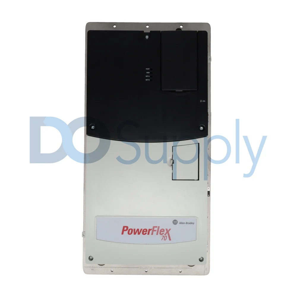
For example, PowerFlex 700 and PowerFlex 70 utilize parameter 161 [Bus Reg Mode] to configure how the drive responds when the DC bus voltage approaches predefined overvoltage limits. This parameter allows the two PowerFlex drive series to be configured for different application and motor braking requirements.
The available DC bus regulation modes in PowerFlex drives include:
- Adjust Frequency Mode: This setting enables only the DC bus voltage regulator. By modifying the output frequency, the drive reduces the regenerative energy returned to the DC bus from the connected motor, preventing the DC bus voltage from exceeding the predefined overvoltage threshold. Conversely, when the DC bus voltage decreases, the PowerFlex drive reduces its power consumption by reducing the output frequency, which helps stabilize the DC bus voltage. This DC bus voltage regulation technique is well suited for applications in which slight, short-duration speed variations during regenerative events are acceptable.
- Dynamic Brake Mode: This mode completely disables the DC bus voltage regulator while activating the Dynamic Brake Regulator. The PowerFlex drive utilizes the specific turn-on and turn-off thresholds to respond to the DC bus voltage approaching the predefined thresholds. When the DC bus voltage surpasses the turn-on threshold, the brake transistor fires, dissipating energy through an external resistor bank. This regulation mode and configuration is an excellent choice for PowerFlex systems requiring uninterrupted and strict speed control during deceleration
- Both–Frequency First Mode: This setting enables both the dynamic brake regulator and DC bus voltage regulator (frequency adjustment), with priority given to frequency regulation. When the DC bus voltage begins to increase rapidly during regenerative operation, the drive first adjusts the output frequency to reduce the amount of regenerative energy returned to the DC bus.
If frequency regulation alone is insufficient to maintain the DC bus voltage within its allowable voltage limits, the dynamic brake mode is activated to dissipate the excess energy. This layered voltage control strategy minimizes the use of dynamic braking while maintaining a stable DC bus voltage during both moderate and extreme regenerative events. During extreme power surges, the dynamic brake serves as a backup while the frequency adjustments manage moderate regenerative energy.
- Both-DB First Mode: In this mode, both regulators execute concurrently, with the dynamic braking circuit prioritized over the frequency adjustment. This mode is critical where frequency adjustments restrict the use of process constraints, especially in applications where speed regulation is rigid.
Thresholds and Protection Limits
To ensure reliable drive operation and prevent nuisance faults or hardware failure, it is important to take note of the DC bus voltage thresholds used by PowerFlex AC drives. Each PowerFlex drive series features distinct predefined undervoltage and overvoltage protection limits, as well as DC bus regulation thresholds that trigger protective control actions when the DC bus voltage approaches unsafe operating levels.
The following table summarizes the typical DC bus voltage thresholds—including nominal operating, DC bus regulation, overvoltage, and undervoltage trip voltage values—for the PowerFlex 700 and PowerFlex 70 drive series at common input voltage classes.
| Drive Voltage Class | AC Input Voltage (RMS) | Nominal DC Bus Voltage | DC Bus Regulation Threshold | DC Bus Overvoltage Trip | DC Bus Undervoltage Trip |
| 200 V Class | 200-240 V | ≈ 324V DC | ≈ 390 V DC | ≈ 405 V DC | ≈ 190V DC |
| 400 V Class | 380-480 V | ≈ 540 to 648V DC | ≈ 750 V DC | ≈ 810 V DC | ≈ 390V DC |
| 600 V Class | 500-600 V | ≈ 810V DC | ≈ 950 V DC | ≈ 990 V DC | ≈ 490V DC |
A PowerFlex 70 or PowerFlex 700 drive generates Fault Code 4 (Undervoltage) when the DC bus voltage drops below the predefined undervoltage limit, typically indicating insufficient AC line voltage or a loss of input power. Conversely, Fault Code 5 (Overvoltage) is generated when the DC bus voltage exceeds the predefined overvoltage threshold, usually due to excessive regenerative energy being returned to the PowerFlex drive from the connected AC motor.
For a 480 V-class PowerFlex drive, DC bus regulation typically begins when the DC bus voltage reaches approximately 750 V DC, at which point the drive adjusts the output frequency to limit the rise in bus voltage. If the DC bus voltage continues to increase and the specific PowerFlex drive is equipped with and configured for dynamic braking, the dynamic brake is typically activated at approximately 780 V DC to dissipate excess regenerative energy. If the DC bus voltage continues to rise despite the activation of the two regulation modes, the PowerFlex drive will initiate an overvoltage trip (Fault 5 code) when the DC bus voltage reaches approximately 810V DC.
Common DC Bus Configuration
Many PowerFlex drive families and configurations can be incorporated into common DC bus systems; whereby multiple compatible PowerFlex drives are interconnected through a shared DC bus. The configuration facilitates direct transfer of electrical energy from regenerating PowerFlex drives (such as those managing overhauling loads or decelerating) to other PowerFlex drives operating in motoring mode, instead of the energy being dissipated as heat through dynamic braking resistors.
During regenerative operation—for example, when decelerating a high-inertia motor or lowering an overhauling load—a PowerFlex drive converts the motor’s potential or kinetic energy into electrical energy and feeds it onto the common DC bus. At the same time, PowerFlex drives operating in motoring mode can draw this regenerated energy from the common DC bus to power their motors. By redistributing the regenerated energy within the PowerFlex drive system, a common DC bus helps reduce the total amount of power drawn from the utility grid, minimize reliance on external dynamic braking resistors, and improve the overall energy efficiency of the system.
However, if the total regenerated energy exceeds the overall power required by the motoring PowerFlex drives, the net surplus energy cannot be returned to the utility through a standard diode-bridge; it must either be dissipated as heat through the dynamic braking resistors or fed back to the incoming AC line supply using an Active Front End (AFE) rectifier or a specialized regenerative line supply.
Applications of a Shared DC Bus Configuration
- Material Handling Systems: Applications such as automated storage and retrieval systems (AS/RS), load transfer equipment, and conveyor systems involve repetitive load transfers and frequent start-stop cycles. A shared DC bus configuration in such applications enables regenerative energy produced during the frequent braking or deceleration cycles to be transferred to PowerFlex drives operating in motoring mode. This helps reduce overall power consumption and improve system efficiency.
- Elevators and Hoists: In multi-drive hoisting and elevator systems, PowerFlex drives operating in regenerative mode—like those controlling lightly loaded ascending cars or descending loads—return regenerated energy to the common DC bus. This regenerated energy is then transferred through the common DC bus to the PowerFlex drives operating in motoring mode (e.g., those lifting heavier loads). This helps reduce the total amount of power drawn from the utility grid as well as improve the overall energy efficiency of the PowerFlex drive system.
- Cranes and Overhauling Loads: Substantial regenerative energy is produced during lowering cycles and heavy lifting; other PowerFlex drives in motoring mode can reuse this energy.
- Centrifuges and Winders: Slowing down high-inertia machinery produces surplus regenerative energy which can be redirected to other PowerFlex drives, thereby minimizing heat loss.
- Industrial Automation Lines: Multi-drive systems in textile, printing, and packaging industries lower both installation and operational costs by reducing/eliminating the need for dynamic braking resistors and duplicate rectifiers. Instead these continuous-process industrial systems employ common DC bus configurations to share regenerative energy between multiple PowerFlex drives.
Picking a PowerFlex drive doesn’t have to be difficult. At DO Supply, our customer service team is ready to help you find the right drive for your application. We also back our products with a two-year warranty. So for your PowerFlex drives and accessories needs, let DO Supply be your one-stop shop for all things automation. If you would like to learn more about drives, we have a more thorough comparison of regenerative and non-regenerative drives here!
DO Supply Inc. makes no representations as to the completeness, validity, correctness, suitability, or accuracy of any information on this website and will not be liable for any delays, omissions, or errors in this information or any losses, injuries, or damages arising from its display or use. All the information on this website is provided on an "as-is" basis. It is the reader's responsibility to verify their own facts.