Why Input Reactors Can Save Thousands in Drive Repairs
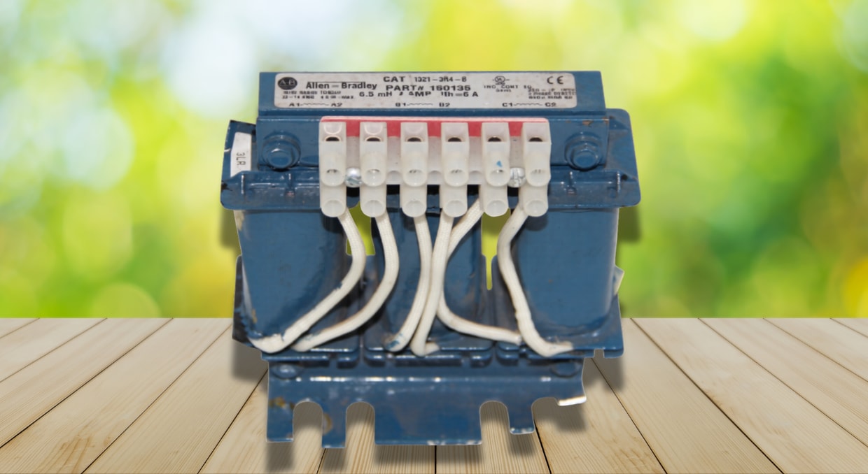
Modern motor control relies heavily on variable frequency drives, yet the components that safeguard them are often the first to suffer budget cuts. Line reactors, also known as input reactors, are often seen as optional add-ons rather than necessary safety measures. The electrical mechanics underlying reactor protection, the failure types that reactors avoid, and the cost justification for implementing them on each drive installation are all discussed in this article.
Understanding the Role of Input Reactors in Drive Systems
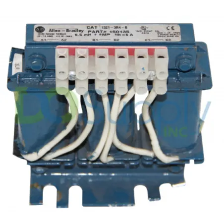
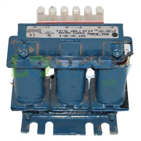
In simple terms, an input reactor is a three-phase inductor placed between a drive’s input terminals and the incoming AC power source. Its purpose is surprisingly straightforward: it increases the line’s impedance. In a drive environment, this impedance smooths out the abrupt current spikes that occur each time the drive’s rectifier bridge charges its DC bus capacitors, as it resists rapid current changes.
Drives convert incoming AC to DC using an SCR bridge rectifier or diode. Because the current is drawn in brief, high-amplitude pulses near the peak of each AC half-cycle rather than as a continuous sine wave, this rectification process is intrinsically nonlinear.
How Voltage Transients Damage Drive Components
Industrial power systems are rarely clean. Voltage disturbances are introduced into the supply by utility switching operations, energization of capacitor banks, and switching transients from other drives and variable-speed loads on the same bus. Because its rectifier and DC bus create a low-impedance channel that transients may take advantage of, drives are especially susceptible to these transients.
When a transient gets to the input terminals of the drive without any problems, it can:
- Instantaneously overvoltage the rectifier diodes, resulting in junction failure.
- Increase dielectric wear by overcharging the DC bus capacitors over their rated voltage.
- Cause annoying overvoltage problems that stop production even in the absence of irreversible harm.
- Produce voltage notching that interferes with nearby equipment’s control electronics
Before these transients reach the rectifier, an input reactor absorbs them and restricts their rate of increase. As a first line of defense, the additional inductance transforms a rapid, harmful spike into a slower, more controllable increase in current and voltage that the drive’s internal protective circuitry can handle.
The Mechanics of Harmonic Current Reduction
Harmonic mitigation is one of the most frequently cited advantages of input reactors, and the underlying process warrants further investigation. Narrow pulses of current are drawn by a typical six-pulse rectifier without line impedance, resulting in a current waveform rich in low-order harmonics, mainly the fifth, seventh, eleventh, and thirteenth. On an unprotected drive, total harmonic distortion of current (THDi) can easily exceed 80-100%.
These current pulses become flatter and wider when a reactor with an impedance of 3-5% is added. This is directly related to the harmonic content mathematically: the harmonic spectrum decreases in magnitude across almost all orders as pulse width increases and peak amplitude decreases. THDi is often reduced from over 80% to between 30% and 40% using a 3% reactor. This is pushed further with a 5 percent reactor, frequently into the mid 20s or low 30s.
Because harmonics do not remain confined within a single driving circuit, this is important. They increase the harmonic load on transformers, generators, and other sensitive equipment that share a bus as they propagate back through the building’s electrical distribution system.
Protecting the DC Bus Capacitors from Premature Aging
The lifespan of DC bus capacitors is strongly correlated with the ripple current and inrush stress they experience, making them a failure point in the drive. Internal heating from ripple current progressively dries up the electrolyte, raising equivalent series resistance and decreasing capacitance over time. This is the well-established mechanism by which electrolytic capacitors age.
The capacitors are forced to absorb a greater portion of the instantaneous charging current for each rectifier charging pulse that hits them without being softened by line impedance. This increased ripple current immediately results in a shorter capacitor life expectancy over months and years of operation. Even small decreases in peak current, such as those provided by a 3% reactor, can significantly increase service life since capacitor life has a nearly exponential relationship with operating temperature and ripple current.
Given that a full capacitor bank replacement, along with the associated labor and downtime, frequently costs more than the reactor itself, this alone often justifies the investment.
Input Reactors and Notching Suppression on Shared Buses
Voltage notching occurs when a drive’s rectifier bridge suddenly short-circuits two phases during commutation, bringing the line voltage down to almost zero. This notch shows abruptly on a bus with no series impedance between drives, and it can spread to all other devices sharing that feeder, including instrumentation power supplies, sensitive PLCs, and HMIs.
Input reactors expand and deepen the notch by increasing the source impedance perceived by the commutation event. This is frequently the determining element in whether nuisance trips and control system issues arise in multi-drive setups, a typical arrangement in SCADA-integrated facilities operating multiple VFDs off a shared MCC lineup. Facilities that skip reactors on even a subset of drives frequently trace intermittent PLC resets or HMI communication faults back to notching from unprotected units.
Comparing Input Reactors to DC Link Chokes
Since input reactors and DC link chokes have similar yet distinct functions, it’s important to distinguish between them. After rectification, the ripple current is filtered by a DC link choke positioned between the rectifier and the DC bus capacitors. For a given impedance value, it is typically more compact and marginally more efficient in lowering capacitor ripple current.
On the AC side, an input reactor is positioned in front of the rectifier. It has an advantage over the DC choke because its placement shields the rectifier diodes from incoming transients and provides resistance to line-side disruptions before they reach the power conversion stage.
A DC choke is currently a common internal component of several drive manufacturers. In situations like these, an external input reactor can still offer significant additional protection against line-side events that a DC choke cannot handle on its own.
Sizing Input Reactors Correctly for Drive Applications
In relation to the drive’s rated voltage and current, reactor size is usually specified as a percentage impedance, most frequently 3% or 5%. While oversizing a reactor results in a needless voltage drop that may impact motor torque availability at full load, undersizing a reactor reduces its protective advantage.
Important factors to consider when sizing include:
- Matching the drive’s rated input current, not the motor nameplate current, to the reactor’s continuous current rating.
- Taking into consideration the installation site’s ambient temperature, as reactors are often rated for an ambient temperature of 40°C and derated above that.
- Choosing 5% impedance reactors for systems with lengthy feeder lines, adjacent capacitor bank switching, or known power quality problems.
- Verifying that the voltage drop introduced by the reactor, typically 2 to 4 percent at full load, does not compromise the required motor torque at the top of the speed range
Engineers should also confirm the reactor’s placement relative to other line-side devices, such as EMI filters, since the installation order affects the assembly’s overall filtering performance.
Best Practices for Specifying Input Reactors on New and Retrofit Projects
Prioritizing reactor installation on drives with documented histories of repeated capacitor or rectifier failures, drives on buses with known power quality issues, and drives feeding critical processes where downtime costs are highest is a practical strategy for retrofit projects on existing drive fleets.
To enable engineers to link reactor presence to future failure rates, documentation should include the reactor impedance %, current rating, and installation date, in addition to the drive’s maintenance record.
This data-driven strategy transforms what is frequently viewed as a one-time purchase decision into a quantifiable dependability program, providing engineering and maintenance teams with hard data to support future budget requests. A well-documented failure mechanism is addressed by the modest, well-understood device known as input reactors. One of the most economical reliability choices for any facility with many drives is to consider them as standard equipment rather than optional additions.
Final Thoughts
In conclusion, input reactors address an issue that many facilities are unaware of until a drive malfunctions. Impedance-limited inrush current, decreased harmonic distortion, transient absorption, and notching suppression are well-known methods that prevent some of the most costly repairs a drive may encounter. When a drive operates without sufficient line-side impedance, rectifier bridges, DC bus capacitors, and power modules are at higher risk of failure. The small initial expense of properly specifying reactors is far outweighed by the cumulative cost of recurring repairs across a fleet of unprotected drives.
If you are looking for a line reactor to protect your drives, or even a new drive to better suit your motion control needs, stop by our site at DO Supply! We carry PowerFlex drives, Allen-Bradley line reactors to match, and so much more. All of our products ship fast and with our two year warranty. Give us a call today and see what we can DO for you!
DO Supply Inc. makes no representations as to the completeness, validity, correctness, suitability, or accuracy of any information on this website and will not be liable for any delays, omissions, or errors in this information or any losses, injuries, or damages arising from its display or use. All the information on this website is provided on an "as-is" basis. It is the reader's responsibility to verify their own facts.