Fieldbus – What Is It?
For many years, industrial networks were connected using RS232 serial communications, which was limited by only allowing devices in a network to communicate via direct serial connections. This means that if there are N devices per connection, then there would be (N-1) connections available for other communications within the industry. However, in the late 20th century, the Fieldbus International Standard was developed, which marked a significant turning point in connecting these networks, allowing for greater flexibility and scalability than previous technologies did allow for.
Fieldbus is a network of computers embedded in various machines at work sites. They allow Input Devices (such as Ethernet Switches and Sensors) to communicate with Output Devices (Valves, Drives) without attaching them to an individual Controller.
In summary, Fieldbus systems provide an efficient way to connect different devices to a single industrial network and make it easy to control them at every production stage. The following guide will evaluate a Fieldbus system, the essential components of this type of field, and some specific implementations of this technology.
Fieldbus in the Complex Automated Industrial System
Complex automated industrial systems typically have many hierarchy levels in their organizational structure. Most generally, the top management levels manage business strategies for production. They are connected to lower-level programmable logic controllers (PLCs) through a non-time-critical communication system such as an Ethernet cable. However, at these low levels, there is often also a need for machines to be able to communicate quickly with one another, so they use Fieldbus instead. This communication links PLCs at the direct control level with elements inside buildings, such as sensors, actuators, electric motors, switches, and valves. Fieldbuses take over from other forms of connectivity like wires or digital I/O signals that would otherwise connect each machine one by one in series down the line.
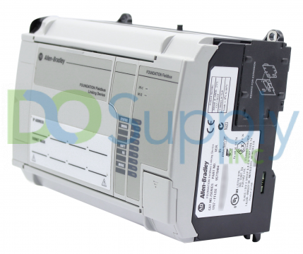
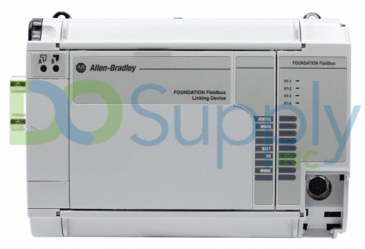
Fieldbus Cards
These Fieldbus cards connect to pCO sistema family controllers via serial links using standard or proprietary protocols, enabling one to access this information and send commands. To efficiently manage units, organizations offer these Fieldbus cards in various options depending on one’s required protocol.
Common Fieldbus Protocols
Industrial buyers should decide what protocol they want when purchasing a Fieldbus product. Once they decide on the protocol, they can look at other aspects, such as how well it fits with their system or network, its physical specs, and its performance specs which will allow them to find the best option that suits their needs.
Currently, there are yet-to-be-agreed-upon standards for Fieldbus architectures. Henceforth, the protocols vary depending on what application or industry they’re going to be used for. The most common protocols found in these systems are Fountain Fieldbus, Device Net, Modbus, Profibus, and so forth.
A diverse range of Fieldbus protocol options developed over time because of the ever-competing Fieldbus manufacturers looking for ways to outdo one another. A need to establish a field bus that would suit individual needs, paired with large markets created by these buyers, led to many different protocols being released. Nowadays, there are two primary choices – Foundation Fieldbus and Profibus – that control systems designers often consider when determining what kind of communications module they want to use. However, not all modules will work with every type of protocol, so keep this in mind when deciding which option is best for any system.
Design Specifications
Design specifications of Fieldbus products involve the number and types of connections they allow. This is an essential consideration in determining process compatibility.
- Max Connections: The number of ports available or connections that components and devices can make.
- Connection Type(s): The cables and connection types are compatible with the field bus, including coaxial and fiber-optic cabling.
- Modularity: It relates to versatility in product design. Modular Fieldbus products are designed with classic pieces which allow for additions and expansion, such as input/output slates (IOS).
Performance Specifications
Performance specifications characterize the degree to which a Fieldbus product functions correctly. Specifications that should be considered include accuracy and drift.
- Accuracy can quantify or qualify how closely measurements come to their actual values—a property increasingly critical as many devices take readings, too.
- Drift measures changes in accuracy over time; devices with high drift will eventually stop working as intended because of this variance. It’s usually characterized by a deviation over one year (±0.10°C).
Features and Capabilities
Fieldbus products have many communication options, such as measuring, calibration, data analysis, and PID control.
- Measuring functions may be incorporated into Fieldbus products instead of some simple sensors or probes that provide intermittent or continuous information about process conditions.
- Calibration Fieldbus devices auto-correct for component drift or temperature-related calibration errors.
- Documenting functions may be incorporated into Fieldbus products to automatically handle and store information from all connected components.
- Fieldbus products may also add data analysis capabilities for aggregate data analysis from all connected components.
- Finally, an option known as PID control may also exist on certain Fieldbus products. PID control serves less as passive couplers but instead provides local data processing without relying on a central PLC.
Functions of Fieldbus
Fieldbus is a set of standards for sensors, actuators, and analyzers that was developed to make real-time data acquisition happen more efficiently.
4-20mA (MIL) devices use analog signals to send plant information back up the chain – this technology has been replaced by newer digital formats transmitted through Fieldbus. With these protocols moving from centralization to distribution, it offers a level playing ground where process control can reside in field devices rather than at the controller or master busbar – which means more brilliant equipment capable of running longer without error. This creates an opportunity for wireless remote monitoring over long distances – even across continents!
How Fieldbus Works
Fieldbus permits multiple field devices to access a single central data transmission point instead of restricting communications to only two at a time. The primary hub then talks with the control center, effectively disseminating vital information during the procedure.
Fieldbus typically communicated via short packets delivered consecutively, time-multiplexed for adequate space consumption, and encoded. In contrast to parallel transmissions, this communication style requires fewer connections since point-to-point interconnections between field equipment and control centers are effectively eliminated. This centralized link offers hundreds of points from which data may flow back and forth from any machine or device engaged instead of simply two connections.
Levels of a Fieldbus System
One must first take notice of what Fieldbus networks are made up of to understand their intricacy completely.
From the least complicated to the most sophisticated, the four layers of a Fieldbus system are Sensor Bus Network, Device Bus Network, Control Bus Network, and an Enterprise Bus Network.
- Sensor Bus Networks: A sensor bus network is the foundational component of a Fieldbus system. These networks convey controller output signals to alarms, indication lamps, or other actuators by connecting several necessary field devices, such as limit switches or level optical sensors, via a single wire.
- Device Bus Network: This level of networking connects many sensors and actuators, including some devices for variable speed drives or motor control centers that give individual components within the system autonomy over their operations. It functions similarly to the sensor bus network but on a much larger scale.
- Control Bus Network: These networks, which employ PLCs and intelligent instruments to provide complete setup and control over devices that can be accessed via human interface panels, function at the most significant levels of complexity (HIP).
- Enterprise Bus Networks: Also referred to as the information-level network, this service connects all employees and computers and handles large-scale data collecting, file sharing, and other tasks.
Different Fieldbus Network Topology
Depending on the kind, an Industrial Fieldbus’ component arrangement may change. Most Industrial Fieldbus layouts consist of:
- Ring Topology: In this kind, each node is linked to two others, one on either side, providing a continuous and circular channel for data to go through.
- Line Topology: Also known as Daisy Chain or Bus Topology, Line Topology is made up of nodes connected one after the other, starting with the first.
- Star Topology: A central hub serves as a conduit for data transmission and connects all connected devices in a star topology.
- Tree Topology: Tree Types/Branches are made up of star networks connected by line topologies, like the branches of trees.
Benefits of Fieldbus
Fieldbus technology has changed many facets of industries, some less profound than others. Let’s look at significant ways this revolutionary invention has enhanced the efficiency of industrial networks.
- Reduced cabling requirements: One highly touted benefit of Fieldbus systems is that they require fewer cables to operate than in a parallel wiring configuration. So rather than having one cable per device, every few hundred devices can connect through one point on the Fieldbus controller. And since it takes just one cable per node rather than per device on average, the distance between nodes is shortened drastically – making setup much quicker and easier overall!
- Lower costs: Furthermore, a reduction in installation time due to easier installation translates into lower operating costs over time too!
- One significant benefit of Fieldbus systems is how easy they are to install. Compared to parallel wires, Fieldbus has shorter cables, and therefore, it takes less time and effort to set up these types of cables during an installation process.
- These systems are also known for having increased reliability as opposed to parallel wiring – since they use short signal pathways. They can avoid problems with fluctuations which makes them ideal when dealing with analog values (continuous values rather than coded).
- These parts work together well because each supplier deals with their device- so different devices from various manufacturers can work together without any trouble or conflicts between one another.
- Other benefits include the possibility for flexibility in its implementation- such as showing all data transmitted from controllers on screens, etc.
- The increased field information includes processed data, averages, minimums, maximums, diagnostics, and operational information.
Critical Advantages for Industrial End-users’ Foundation
The Fieldbus offers several significant advantages, particularly for different sectors. These benefits include:
- Control-in-the-field, first (device-to-device communication)
- Closed-loop management (sensor feedback)
- Lessened cable (multiple devices per cable)
- Minimal hardware (via VirtualMarshalling)
- A smaller overall system footprint (with fewer I/O cards, gadgets, wires, etc.)
- Reduced number of devices (multivariable devices)
- accelerated commissioning (compared to traditional approaches)
- Stricter control restrictions (via a control in the field)
- Improved diagnosing (via higher power availability and signal status)
- Simple online updates
Function Blocks in Fieldbus
Function Blocks are used by the User Layer, which also offers device configuration. Function Blocks are utilized in a device for control, diagnostics, safety, and production accounting purposes and describe items such as:
- Names for Standardized Parameters
- Types of Data
- A user-friendly cascade initialization mechanism.
- Capabilities for Status Propagation.
- A windup prevention mechanism.
- A Trend Collection Mechanism with Built-In Status Propagation Rules And Analysis Tools!
- Mechanisms for scheduling execution that minimize production time waste and prevent block interference!
These include:
- Standardized function blocks are among them.
- Vendor-customized and vendor-enhanced function blocks.
Resource Blocks in Fieldbus
Each device also has a Resource Block, which includes information on the actual item, such as the Manufacturer ID.
- The kind of gadget.
- Editing.
- Free space and memory use.
- Processing time.
- The condition of the device.
Transducer Block in Fieldbus
Each device has a Transducer Block, which stores the sensor’s or actuator’s parameter(s).
Device Description Language (DDL) in Fieldbus
The Function Blocks, Transducer Blocks, and Resource Blocks are not just limited to a standardized set of parameters. The latest DDL offers manufacturers the chance to add specific attributes that go beyond this limit – things such as names, data types, enumerations, units, valid ranges, user entry limits, entry conditions (such as out-of-service or manual mode), connection properties, presentation information and help text. These changes can be easily made with DDs (device descriptions), a compiled form of DDL; updates can then be downloaded onto the equipment for easy installation and bug fixing.
Control in Fieldbus
The two key advantages of the Fieldbus system are its distribution of control and concurrent processing. In a traditional DCS system, these aspects are centralized within the controller, whereas with a Fieldbus system, they’re distributed throughout each device. The following actions take place – at least in theory – automatically via programming:
- Two input blocks
- Two output blocks
- Six control blocks, such as PID
Other less often used control functions include pulse input, dead time intervals, arithmetic, splitting up data streams into various channels for more straightforward analysis/interpretation by operators & characterizing signals for a display to make them easier to read or understand.)
Most current control systems use a distributed control system (DCS) to regulate processes. Smart transmitters will allow this regulation to happen on the transmitter, moving it away from the controller. This prevents overloads for the controllers and makes it easier for newer functions that require more data than what was traditionally needed before. Controlling with Fieldbus is relatively easy if devices are installed at or close to each other since they are designed for local networks; connections only need to travel across one network segment instead of several.
Messages on the bus usually consist of two classes:
- Cyclic: When using 31.25kbps Fieldbus technology, these messages involve process data being transmitted across connected function blocks and can be a network member.
- Acyclic: these are single data transmissions that depend mainly on scheduling by an individual device’s controller.
New Installations and Upgrades
Fieldbus is more advantageous for new installations since it reduces the cabling needed to reach one’s whole plant and provides more information than other protocols. As long as both Fieldbus devices abide by a standard, any vendor’s equipment can be used together- even if one already has one installed on an old installation. When upgrading from old systems, one likely finds that there will be some costs associated with updates or replacements, but when replacing equipment that has already failed, one won’t need too much done since all one would need is software updates.
DCSs have received a lot of investment. Fieldbus will require integration with current DCSs to be successful. The DCS now does high-level management instead of low- and high-level control, leaving Fieldbus devices to handle low-level control. The following tasks will be transferred from the DCS to Fieldbus:
- Process variables
- Create an alarm.
- Data on calibration.
- Status of the device.
- Area management.
To accomplish this, the DCS oversees high-level control functions and regional interoperability. As a result, its primary duties continue to be:
- Advanced Management
- Control of Interarea (bring together all area controls)
- Coordination of the production.
- Configured Centrally.
- Filtering of alarms.
- Network management.
- Communicating with devices and services to understand their needs.
- Keeping a Global Database.
DO Supply Inc. makes no representations as to the completeness, validity, correctness, suitability, or accuracy of any information on this website and will not be liable for any delays, omissions, or errors in this information or any losses, injuries, or damages arising from its display or use. All the information on this website is provided on an "as-is" basis. It is the reader's responsibility to verify their own facts.