MicroLogix PLC Troubleshooting and Maintenance: How to Keep Your System Online
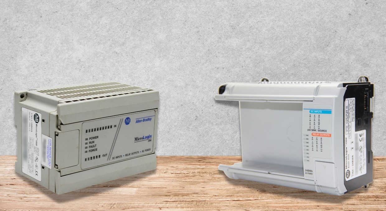
If you work as a maintenance tech or plant engineer, you know the Allen-Bradley MicroLogix PLC. It’s everywhere in industrial automation, and for good reason; though, even the best equipment needs some care. Troubleshooting and regular maintenance help keep it in working condition. Here’s a guide that cuts through the jargon and turns those official specs into real-world advice you can actually use.
Essential MicroLogix Maintenance Practices
The first and by far the most effective ‘line of defense’ against sudden system failures is good old proactive maintenance; after all, a well-maintained MicroLogix controller is just much less ‘likely’ to develop those catastrophic faults that cause so much production loss.
All maintenance tasks must be carried out by a qualified technician familiar with the dangers of industrial control systems. Conduct pre-work maintenance when the power of a MicroLogix system is off and disconnected from all sources.
The operating environment plays another critical role in physical maintenance. Every ventilation passage should remain open and unblocked. If your MicroLogix enclosure’s auxiliary cooling accumulates dust, the filter should be frequently changed or replaced. Set a regular schedule to turn off the system and carefully clean out any dust and grime. Pay attention to everything, from the semiconductor auto-flush to the lid. Dust and dirt can stop the system and its components from working altogether. Additionally, conduct periodic inspections for wear or damage, and ensure proper grounding at all times.
The MicroLogix controller uses a lithium battery (usually 1747-BA) to retain its program in the event of a power failure. If you see a solid red BATTERY LOW light, swap that battery right away. Lithium batteries can be tricky since they’re full of reactive stuff, so handle them carefully and get rid of old ones the way your supplier tells you. Sticking to these steps, as recommended by NEMA Standards Publication ICS 1.3-1986, keeps your MicroLogix equipment running smoothly.
Common MicroLogix Faults and Error Codes
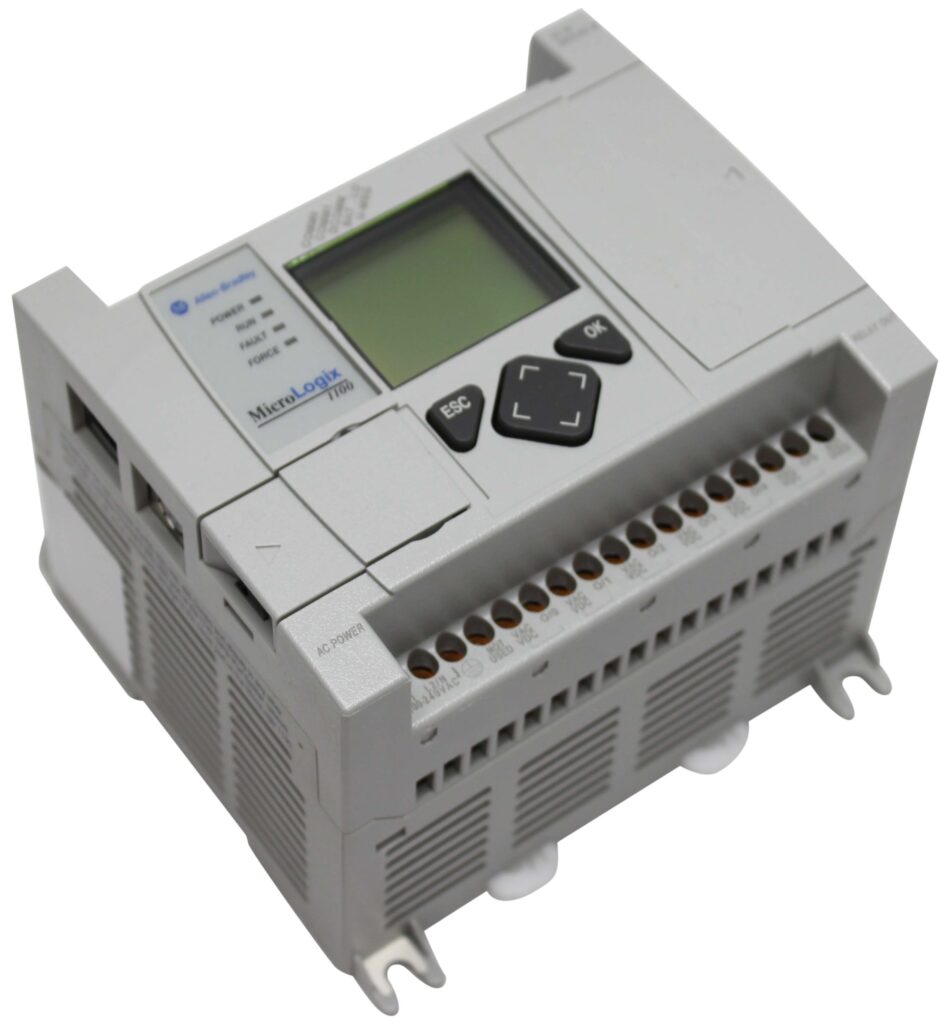
When a fault occurs, the MicroLogix status indicators give an immediate diagnosis. Understanding these LED patterns is of the utmost importance.
Decoding the Status Indicators
- POWER Indicator: Normal power operation is confirmed by a steady green light. If the light is off, the MicroLogix controller is not receiving power, or the power supply is faulty.
- RUN Indicator: The MicroLogix is actively executing its logic program. The controller is in Program or Test mode if the light is off.
- FAULT Indicator: This is your main error signal. A user program fault, such as a logic error, is indicated by a flashing red light. A steady red light indicates a hardware or critical configuration fault within the MicroLogix processor.
- FORCE Indicator: A steady amber light means you’ve got one or more I/O forces installed. That’s not a fault, but it’s important to know, because forces take priority over your normal program. When you see the COMM 0 or COMM 1 light flashing green on 1764-LRP models, you’ve got active communication going on.
- COMM Indicators: The DCOMM indicator tells you about the communication mode. If it’s a steady green, your MicroLogix is running with its default settings.
Diagnosing Error Conditions from LED Patterns
If all LEDs are off, it indicates a complete power failure. In such a case, ensure proper connection of the line power, and the voltage is within the MicroLogix allowable range. Look for tripped breakers or blown fuses. It may also indicate overloading.
If the POWER LED is On Steady, and the FAULT LED is On Steady, it is a hardware failure. More often, this will point to a processor hardware error or perhaps loose wiring. Try power-cycling the MicroLogix. If it doesn’t clear, check every power and I/O connection and make sure they’re all tight. If the fault stays then, chance is the hardware’s gone bad. Call technical support at that time or call us and schedule a repair. We fix automation equipment in-house and even offer a 2-year warranty on top of our excellent service!
If the POWER LED is On Steady, FAULT LED is Flashing Red, the fault is related to the application or program. This is the one you’ll run into most. The MicroLogix caught a major error—either in your user logic, configuration, or something attached to it. Here’s what you do: hook up your programming device and check the Major Error Code in Status File Word S:6. That code will point you straight to the problem, whether it’s a bad instruction in your program or maybe a missing communication module.
A Step-by-Step MicroLogix Troubleshooting Guide
- Start with the LEDs: The first clue something’s wrong is usually a strange LED pattern or the controller refusing to behave. Treat the front-panel indicators as the system’s first “symptom report.”
- Pull the actual fault information: Once you’ve noted the LED behavior, connect your PC and check the Status File (S:6). This is where the controller logs detailed error codes that go far beyond what you can get from blinking lights alone.
- Decide whether it’s hardware or software: Before you dive too deep, split the problem into two buckets:
- Hardware: power issues, loose wires, dead sensors, or a bad expansion module.
- Software: faulty ladder logic, improper mode changes, or an instruction creating a major fault.
- Rule out wiring problems early: If you suspect hardware at all, tug on every terminal. Loose or corroded wires are easily one of the most common causes behind strange MicroLogix behavior.
- Verify the controller is actually powered: Check the POWER LED, If it’s dark, confirm the incoming supply is within the rated range, then check fuses, breakers, or any external power supply feeding the chassis.
- See if the program is running: Look at the RUN LED. If it’s off, the controller isn’t executing your logic. It may be stuck in Program mode or halted because of a major fault. Either situation gives you more clues about where to look next.
- If the FAULT LED is on, go back to the code: A lit FAULT LED means the controller hit something it couldn’t recover from. Use the error code you pulled from S:6 to track down the exact condition, whether it’s an instruction problem, a misconfigured module, or corrupt logic.
- Check the input indicators: The INPUT LEDs should match what’s happening in your field wiring. If a sensor is clearly being triggered but the LED never changes, it’s usually a wiring issue, a dead sensor, or a failed input channel.
- Fix the root cause, then clear the fault: After identifying the real issue, whether it be bad wiring, a dead sensor, or faulty logic, it’s time to fix it. To clear the fault, reset the Major Error Halted bit (S:1/13), or power-cycle the controller if you’ve enabled Fault Override at Power-Up (S:1/8). Clearing the error without fixing the problem will only get you right back here.
- Return the controller to Run mode.
- Once everything is corrected and stable, switch the MicroLogix back to RUN and confirm the LEDs and I/O behavior look normal.
I/O and Wiring Checks for Your MicroLogix System
Input and Output modules link your MicroLogix to the real world, so they’re often where problems start. The INPUTS and OUTPUTS LEDs are your friends here. If the INPUTS LED is steady amber, at least one field input is ON. If a sensor is active but this LED stays dark, your problem’s in the field—maybe the sensor has no power, the wiring’s off, or the input module is failing.
Same idea with the OUTPUTS LED. If it’s amber, MicroLogix is trying to turn something on. If the associated output device does not respond, the problem lies somewhere between the module and the device. Check for blown fuses or bad wiring.
For network issues, watch the COMM LEDs. In a networked MicroLogix setup, a non-flashing COMM light usually indicates communication is down. Check your cables, connectors, and port settings to get things talking again.
Preventing Downtime in Your MicroLogix Application
Firmware Management
Keep your MicroLogix OS up to date. This fixes known bugs and improves stability. Keep in mind that installing new firmware wipes your user program, so always back up first. Make sure the controller’s in Program mode and DCOMM LED is on before you start. During the upgrade, the LEDs do a walking pattern; once it’s done, you’ll see a specific flash pattern. If you get a flashing Run, Force, and Fault LED, your OS is missing or corrupt—re-flash it.
Spare Parts Strategy
For critical setups, keep spares on hand. An extra MicroLogix controller, I/O modules, and a 1747-BA lithium battery will be ideal as backup. Stick with Rockwell parts when you need replacements. That way, everything stays compatible and safe.
When you call Rockwell or your distributor for support, it helps to have a few details on hand:
- The controller’s type, series, and revision
- The processor firmware (FRN) number
- What are all the LEDs doing
- Any error codes from the status file (S:6)
Conclusion
Keeping your MicroLogix controller functional, healthy, and fault-free doesn’t need to be difficult. Routine and preventive maintenance will go a long way toward helping you avoid guides like these. But if you find yourself needing more help or replacement equipment, feel free to call us instead. We at DO Supply can take your old or broken equipment and restore it to a healthy, optimal state, all backed by our 2-year warranty. We also have a wide selection of MicroLogix controllers in stock and ready to be shipped same day for time-sensitive replacements.
DO Supply Inc. makes no representations as to the completeness, validity, correctness, suitability, or accuracy of any information on this website and will not be liable for any delays, omissions, or errors in this information or any losses, injuries, or damages arising from its display or use. All the information on this website is provided on an "as-is" basis. It is the reader's responsibility to verify their own facts.