PLC Design 101: CPU vs Processor and the Role Each Plays in Machine Control
In discussions of CPU vs. Processor, every automation engineer has encountered both terms in the same conversation. In PLC documentation, hardware manuals, and system design discussions, they appear side by side, sometimes interchangeably, sometimes with conflicting meanings. For engineers selecting controllers, writing ladder logic, or troubleshooting scan cycle delays, the distinction is very basic. Understanding exactly what a processor chip is, what a CPU module is, and how they relate inside a PLC gives you a clearer model for hardware selection, performance optimization, and fault diagnosis. This is exactly what we will be discussing in this article regarding CPU vs. Processor.
Defining the Processor in a PLC
In correct PLC hardware terminology, the processor is the physical silicon chip that executes instructions. It is a discrete integrated circuit mounted on the circuit board inside the controller module. This chip fetches each instruction from memory, decodes it, and executes it, one operation at a time, governed by its internal clock frequency. Every rung evaluation, every timer update, every arithmetic calculation in your control program runs through this chip.
The processor chip does not operate independently. It sits alongside SRAM, flash memory, communication ASICs, and power regulation components on the same circuit board. It reads tag data from SRAM during logic execution and stores program results back to SRAM after each instruction. It relies on the flash memory for non-volatile program and configuration storage. The processor chip is the computational engine, but it is one component inside a much larger assembly.
In Allen-Bradley ControlLogix and CompactLogix hardware, this processor chip is a 32-bit or 64-bit core operating at a fixed clock frequency. Its clock speed, instruction pipeline depth, and cache architecture directly determine how fast the scan cycle executes. A faster processor chip with a deeper pipeline can complete more instructions per millisecond, which translates directly into shorter scan times and better responsiveness in high-speed control applications.
Defining the CPU in a PLC
The CPU, Central Processing Unit, is not a chip. It is the entire controller module: the complete hardware assembly that includes the processor chip, onboard SRAM, flash memory, communication ports, I/O interface logic, and the firmware that ties everything together. The CPU is the brain of the PLC. It manages the full cycle of machine control, reading physical inputs, executing the control program, and updating physical outputs, as one integrated, continuously running system.
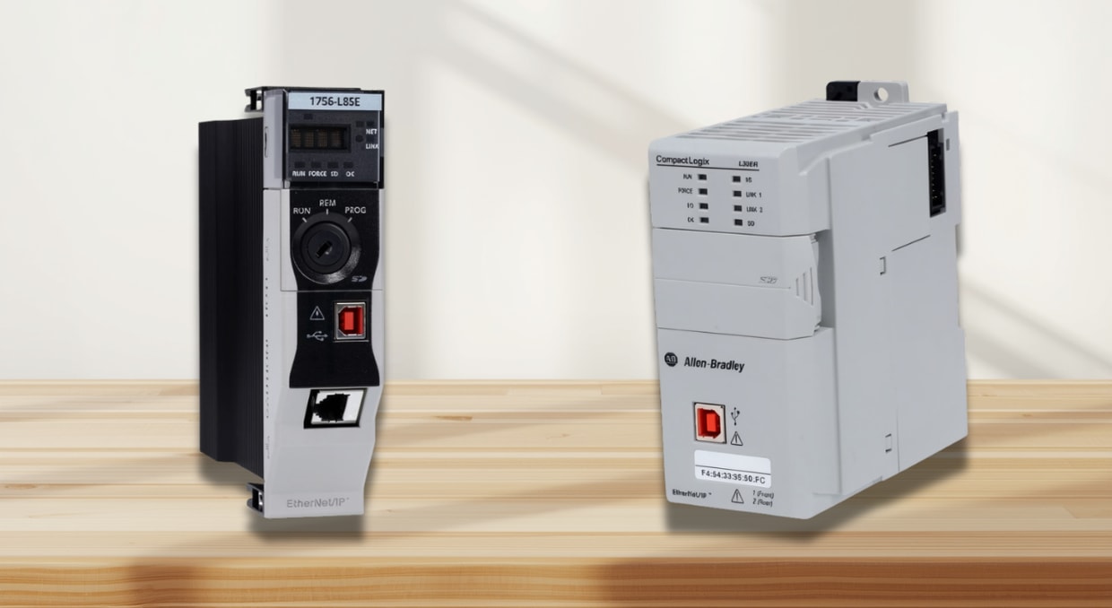
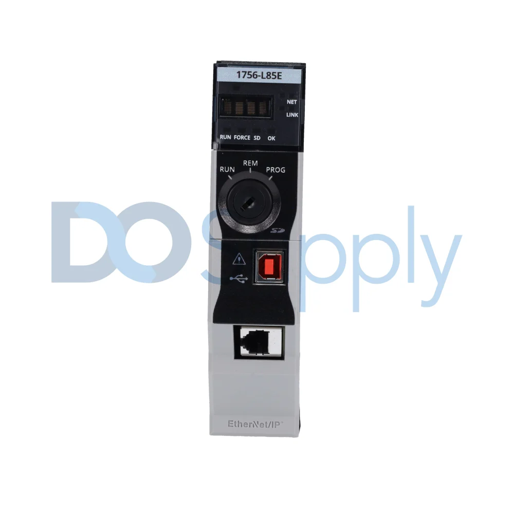
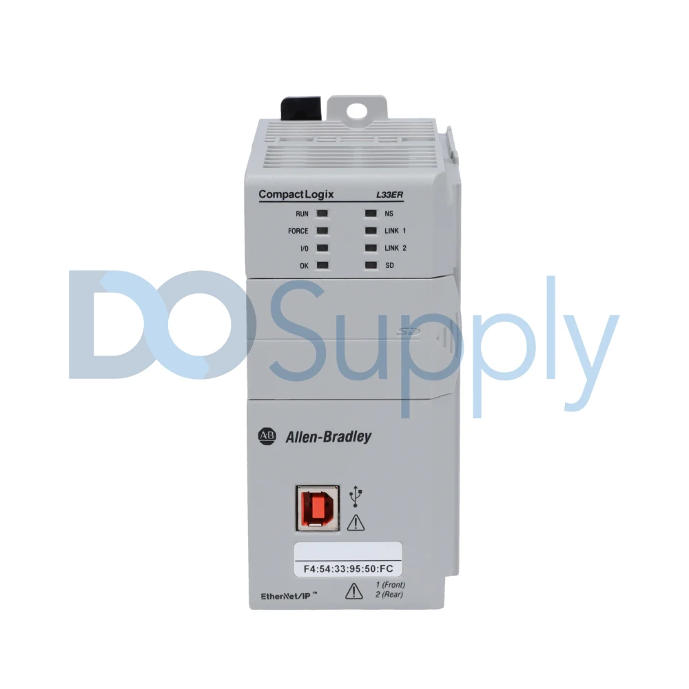
When Rockwell Automation refers to a 1756-L85E ControlLogix controller or a 1769-L33ER CompactLogix controller as the “processor module,” what they are describing in functional terms is the CPU, the complete control unit. This module houses the processor chip at its core, but the module itself is the CPU. It is the unit you order from a catalog, mount in a rack, and connect to I/O and networks. Every specification published in a Rockwell hardware selection guide, memory capacity, number of EtherNet/IP nodes, communication ports, motion axis support, and safety function integration describes the CPU module as a whole, not the processor chip alone.
This distinction matters because it reframes how you think about the hardware. The processor chip sets the raw computational speed. The CPU module determines what speed it can run at, how much data it can store, how many devices it can communicate with, how much data it can process within a given time frame, and how many simultaneous tasks it can manage.
CPU vs Processor: Role Each Plays in Machine Control
Hardware Selection and Module Sizing
In the discussion of CPU vs. Processor, when you specify a controller for a new machine, you are selecting a CPU module. The comparison occurs at the module level: SRAM capacity for the tag database, flash capacity for program storage, the number of integrated EtherNet/IP ports, the maximum number of EtherNet/IP nodes, motion axis support, and GuardLogix safety integration. A 1756-L82E supports up to 5MB of user memory and 175 Ethernet/IP nodes. A 1756-L85E supports up to 40MB of user memory and 300 Ethernet/IP nodes. Both contain processor chips, but the CPU modules they are part of are built for entirely different application scales. Selecting the wrong CPU module at this stage, under-sizing memory or communication capacity, creates hard system limits that logic optimization cannot resolve later.
Scan Cycle Execution and the Role of the Processor Chip
The scan cycle is the repeating sequence the CPU module runs continuously: input scan, program scan, output scan, and communication service. The processor chip inside the CPU module is what drives the program scan phase. It fetches each compiled Logix instruction from SRAM, decodes it, executes it, and writes the result back to the tag data table, all within a defined task period. On a 1756-L85E, Rockwell documents typical Boolean logic scan rates of 0.1 to 0.5 milliseconds per thousand instructions. More complex instructions, PID blocks, motion calculations, and structured text math operations consume proportionally more processor chip cycles per execution. The processor chip speed sets the ceiling on how fast the CPU module can complete each program scan.
Scan Cycle Overruns and Watchdog Faults
Scan overruns occur when the processor chip cannot complete the program scan within the configured task period. The CPU module contains a watchdog timer, a hardware timer independent of the processor chip, that monitors this interval. If the program scan exceeds the watchdog period, the CPU module faults with a Task Watchdog Timeout error, logged as Type 6, Code 1 in ControlLogix diagnostics. Resolving this fault requires reducing the computational load on the processor chip: removing redundant logic, simplifying AOI structures, splitting heavy calculations into separate periodic tasks, or increasing the task period. The CPU module reports and manages the fault. The processor chip’s execution speed is the variable being managed.
Motion Control and Processor Chip Utilization
High-speed motion applications push the processor chip harder than any other control task. In a ControlLogix motion system, the motion task runs at a fixed period, typically 1 millisecond or 2 milliseconds, and the processor chip must complete the entire motion planner execution within that window. The controller’s task monitor displays CPU utilization per task in real time, showing what percentage of each task period the processor chip is consuming. A 1-millisecond motion task consuming 45% of processor capacity leaves 55% for continuous and periodic tasks. When total utilization consistently exceeds 70–80%, motion-axis faults become likely. Keeping steady-state processor chip utilization below 70% is a design rule built on the physical limits of the chip inside the CPU module.
Firmware, Diagnostics, and the CPU Module Interface
The firmware running inside the CPU module defines how the processor chip interprets and executes Logix instructions. Rockwell releases firmware revisions that improve processor chip instruction throughput, fix known execution bugs, add support for new instructions, and refine communication scheduling. Firmware revision 33.x and 34.x for ControlLogix L8 series CPU modules introduced CIP Security improvements and high-availability enhancements implemented through updated processor chip scheduling logic in the firmware layer. When you flash a CPU module to a new firmware revision, you are updating the code that governs how the processor chip runs your control program. This is why firmware version compatibility matters: a project compiled for one firmware revision cannot be downloaded to a CPU module running an older revision without version conversion. The controller’s diagnostics interface displays two distinct layers of information: module-level data (series, firmware revision, available memory) and processor-level chip data (CPU load percentage per task). Both are necessary for maintaining a healthy, stable control system.
Final Thoughts
In conclusion, as mentioned above regarding CPU vs processor,the processor is the physical silicon chip inside the controller, the component that fetches and decodes. It executes every instruction in your control program. The CPU is the complete module that contains the chip. This assembly includes memory, communication ports, I/O interface logic, and firmware, all working together to run the machine control cycle from input scan to output update.
When designing a control system, think at both levels. Select the CPU module based on your application’s memory requirements, communication load, number of motion axes, and safety needs. Then manage the processor chip’s utilization carefully, monitor task load through the controller’s diagnostics, keep utilization below 70% in steady state, respect watchdog limits, and budget headroom for peak demand. Understanding the real difference between CPU and processor in PLC design means you can specify hardware accurately, troubleshoot faults faster, and build machine control systems that remain reliable throughout the equipment’s full production life.
If you are shopping for new automation equipment, then stop on by DO Supply! We carry PLC and PLC processors, accessories, and other industrial automation equipment to match, all from brands you can trust! For added peace of mind, we test all our products in-house and offer a two-year warranty. Have equipment to sell or in need of repairs? Give us a call today and let us help! If you would like to read more, we have an article explaining the different design philosophies of PLC manufacturers here.
DO Supply Inc. makes no representations as to the completeness, validity, correctness, suitability, or accuracy of any information on this website and will not be liable for any delays, omissions, or errors in this information or any losses, injuries, or damages arising from its display or use. All the information on this website is provided on an "as-is" basis. It is the reader's responsibility to verify their own facts.