Drive Component Overview: Precharge Board, Definition and Purpose
Drive Component Overview
In industrial automation, the term “drive” is often associated with motor drives, which are types of motor controllers described using various terms such as Variable Speed Drives (VSDs), Adjustable Speed Drives (ASDs), Inverter Drives, Adjustable Frequency Drives (AFD), Variable Frequency Drives (VFDs), AC Drives, Variable-Voltage Drives, …etc. However, even though these terms are used interchangeably, they have different meanings depending on the technique used to control the motor speed and the drive’s application.
For example, a Variable Speed Drive is a more generic term that applies to electronic or mechanical devices which control either motor speed or the speed of motor-driven equipment like compressors, fans, pumps, etc. Whereas, a VFD is a device that uses power electronics to vary the frequency of the input voltage to a motor, thereby controlling the motor speed. On the other hand, an Adjustable Speed Drive is also a more generic term that applies to both electrical and mechanical means of controlling motor speed. In this article, we’ll focus on Variable Frequency Drives (VFDs).
Basically, a Variable Frequency Drive is an electronic device used to control the speed, torque, and direction of synchronous and induction AC motors, by varying the AC frequency of the voltage supplied to the motor. A VFD also has the capability to control ramp-up and ramp-down speed during motor start-up or stopping, respectively. Thus, you can use a VFD to smoothly start your motor and accelerate it to the required speed at a controlled acceleration rate.
The rapid adoption of industrial automation techniques has increased the need for better process control, resulting in many new applications for Variable Frequency Drives to control the speed and torque of motor-driven machinery. Today, VFDs are widely used to precisely regulate the speed of AC motors in manufacturing processes, conveyor belt systems, escalators and lifts, and cooling systems. Also, VFD-based motor torque control systems are used in water pumps, variable torque fans, and crushers in the mining industry. In addition, cranes and hoists use VFD systems for precise positioning and speed control.
Components of a Variable Frequency Drive
A Variable Frequency Drive consists of three main components, namely: (i) The Rectifier Section; (ii) The DC Link; (iii) The Inverter Section.
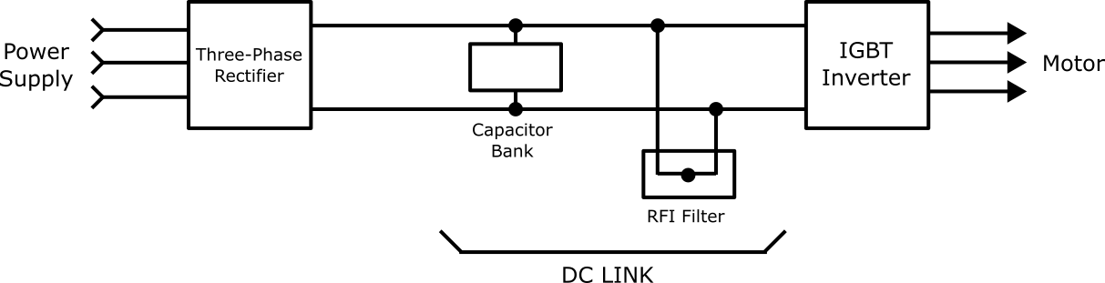
A) Rectifier Section: Also known as the rectifier bridge, this unit consists of electronic components like diodes or thyristors that convert the incoming fixed frequency, fixed-line three-phase, or single-phase AC voltage into unfiltered DC voltage. If diodes are used, single-phase AC conversion would require four (4) diodes in a bridge configuration while 3-phase AC conversion would need a six (6) diode rectifier bridge.
Note: A Thyristor rectifier circuit provides controlled power switching that varies the DC output voltage, but diode full-wave rectification provides uncontrolled power conversion.
B) DC Link: Also referred to as the DC Bus and Filtering section, the DC link consists of L-C filters; a series of Inductors(L) used in conjunction with Capacitors(C) in a parallel configuration. The capacitors filter out frequency-dependent AC ripples to deliver smooth DC output voltage. They also act as voltage surge inhibitors. In addition, DC-Link capacitors also store the filtered DC voltage to be used by the inverter. On the other hand, the series of inductors inhibits current surges within the VFD circuit.
Note: The DC link also includes other types of filters such as RFI (Radio Frequency Interference) filters and harmonic filters, which reduce or eliminate electrical noises and harmonics.
C) Inverter Section: This unit consists of high-power semiconductor switches such as transistors or Insulated-Gate Bipolar Transistors (IGBTs) like MOSFETs or MOS. In most VFD inverters, IGBTs are used to convert the steady DC voltage from the DC-Link into a variable AC voltage with an adjustable frequency. Therefore, an AC voltage signal with a specific frequency can be sent to the VFD-controlled motor as desired.
In addition to the aforementioned three main components, most VFDs also include:
- Control Circuit: This circuit includes an onboard microprocessor. Its responsibility is to coordinate the switching operation of the high-power transistors in the inverter section, as well as control the output frequency and AC output voltage. In short, all VFD programming takes place in the control circuit, which also controls all the operations of the VFD.
- Operator Interface: This could be a type of operator control that allows users or operators to command the VFD-driven motor to function as desired, either through the use of motor control I/O or manually.
- Fuse Section: This unit is designed to protect the sensitive electronics on the VFD circuit and the connected motor from dangerous currents and current spikes.
- Resistors: Some VFDs include resistors that assist in absorbing voltage spikes that would normally go to the AC motor. These resistors also provide a means to bleed down the DC link capacitors when they’re de-energized. This helps to prevent unfortunate accidents as a result of the high voltage stored by those capacitors even when the main power supply is turned off.
Note: DC link capacitors are constantly charging and discharging with every half-wave when AC power is applied to the VFD; so, they can continually discharge high voltage to anyone who comes in contact with them.
- Input Line Reactors: They reduce the electrical noise or harmonics associated with VFDs. Normally, a VFD line reactor minimizes the discontinuity of the input current drawn by the rectifier section. Minimizing this current-draw distortion or discontinuity reduces the harmonic current created by the Variable Frequency Drive.
Also, since a line reactor is installed in front of the VFD system, it assists in protecting the drive from most voltage transients caused by voltage drops within the system.
- Communication Devices: VFDs include communication devices or electronic communication interfaces that allow them to receive command signals from remote sensors, external user interfaces, or an external program.
- Motion Control Features: Motion control VFDs include high-speed input/output ports such as CC-Link, MODBUS, and Ethernet/IP ports for built-in connectivity and feedback. Also, the onboard microprocessor in the control circuit enables the VFD to perform simple single-axis or master-slave motions. For complex motion capabilities, the VFD would require a Programmable Logic Controller (PLC) or a dedicated motion controller.
- Dynamic Braking: When this feature is included, the VFD can control the ramp-down speed of the connected motor to provide a controlled deceleration rate and smooth stopping.
- Housing: VFDs are housed in suitable enclosures to protect them from harsh environmental conditions.
DC Link Pre-charging in a Variable Frequency Drive
As discussed in the previous section, a standard VFD circuit includes a Rectifier, a DC Link, and an Inverter. In the Rectifier unit, incoming fixed frequency, fixed-line AC voltage is converted into DC voltage. The DC Link then filters and smoothens the DC power from the rectifier, while storing a huge amount of electrical capacitance. Finally, the Inverter unit, which is connected in a parallel configuration with the DC Link, converts the steady DC voltage into a variable frequency, variable AC output voltage that is sent to the connected motor.
It’s worth noting that when electric power is supplied to the VFD, the DC link voltage (voltage across the DC link capacitors), rises from zero to the rated value. However, if this rise in the DC voltage was left to take place naturally, it would occur very quickly by drawing huge amounts of electric current from the power supply lines, through the rectifier unit, and into the DC link capacitors. The drawn large amount of current is referred to as inrush current and can be damaging to both electrical and electronic components of the VFD circuit.
Thus, to prevent the VFD components from getting damaged, the rising of the DC link voltage from zero volts (0 V) to the rated value needs to occur in some controlled manner, rather than naturally. This controlled rising of the DC link voltage is known as DC-Link Pre-charging Operation.
Precharge Board: Definition and Purpose
Essentially, a precharge board is a specialty circuit that allows supply current to flow into a system in a controlled manner until the voltage level rises to a value that’s very close to the source voltage. In VFDs, a precharge board is used to limit inrush current, allowing the downstream DC-Link capacitors to charge slowly. Any high-voltage system having downstream capacitance is exposed to damaging inrush current when it’s first turned on. If this inrush current is not controlled and limited, it can result in significant damage to the components of such a system. For example, unmanaged inrush current can lead to damaged connectors, cables, or fuses.
Thus, a precharge board plays a key role in the proper operation and protection of electrical and electronic components in high-voltage applications. In fact, precharge circuit boards increase the service life of electric components and the reliability of the high-voltage system as a whole.
Pre-charging Methods Applied in VFDs
Most Variable Frequency Drives accomplish DC-Link Pre-charging through two different methods. The first method makes use of contactors and resistors that are connected between the input supply line and the rectifier section of the VFD. Whereas, the second method makes use of a rectifier unit with (at least partially) Silicon Controlled Rectifiers (SCRs) or thyristors.
In the first method, two precharge resistors are connected between the input supply line and the rectifier unit using a precharge contactor. In other cases, the two precharge resistors can be connected between the input supply line and the DC link capacitors. Pre-charging introduces a new state in the VFD system called the precharge state. In the precharge state, the precharge contactor and the precharge resistors are included in the VFD circuit. This allows the DC link capacitors to charge slowly to nearly the same voltage as the input power line voltage.
After the precharge state, the precharge contactor opens, excluding the precharge resistors from the VFD circuit. And when the supply contactor is closed, the AC supply line gets connected directly to the rectifier unit. The supply contactor remains closed during the entire operation of the VFD system. Since the DC link capacitors are charged before the precharge resistors are excluded from the VFD circuit, the inrush current is limited to a manageable level and the VFD system gets to operate reliably.
This method provides a means for controlling inrush current in VFDs using simple diode rectifier units. However, it’s not effective in terms of cost and component size, particularly the supply contactor, which can negatively impact the size and cost of the entire VFD system. For this reason, precharge circuit boards made of precharge resistors, a supply contactor, and a precharge contactor are rarely used in VFD systems.
In the second method, the VFD rectifier bridge will have at least one thyristor or SCR in each supply line phase. An SCR is basically a high-power semiconductor that allows electronic control of its current conduction rate. Thus, during precharge, the conduction rate of the SCRs in the rectifier unit is controlled to permit the flow of only small pulses of inrush current. Once precharge is completed, the rectifier’s SCRs are then controlled to conduct current at all times; so, after precharge, the SCR rectifier will act as a diode rectifier.
SCR-based precharge boards are widely used in VFDs. They also have many other industrial-electronic applications such as speed control and reversing both AC and DC motors. Moreover, integrating a diode into the SCR precharge board can provide regenerative capabilities.
What Advantages do Precharge Boards Provide?
- They prevent contact welding. Welded contacts are still a major failure mode of contactors in most high-voltage systems.
- They are helpful in detecting system issues, faulty circuits, or other electrical hazards. For instance, you cannot precharge into a soft-short because the precharge board will detect that the downstream voltage is not rising and it’ll automatically terminate the pre-charging operation.
- In case of a hard-short, the precharge resistors in the precharge board will limit current flow. This will in turn reduce system damage before the fuse clears the hard-short fault.
- In cases where inrush current might be large enough to blow a fuse or trip a circuit breaker. A precharge board may be used to eliminate nuisance tripping of various circuit protection devices.
Other Applications of Precharge Boards
In addition to being a key component of Variable Frequency Drives, precharge circuit boards are also often utilized in onboard chargers and battery management systems of electric vehicles. Though rarely, precharge boards are also used in some industrial applications like utility power supplies and power distribution units.
In electric vehicles, controllers with high-capacitive loads are used to regulate motors. Such systems include High-Voltage (HV) positive and negative contactors that act as an emergency disconnect in case the motor regulator fails. If a precharge board is not used, welding is likely to occur within the contactor as it closes. This can cause brief arcing that leads to contactor pitting, resulting in complete contactor failure or EV system malfunctioning. Also, a precharge board can be very useful every time a hybrid or electric vehicle is turned on.
DO Supply Inc. makes no representations as to the completeness, validity, correctness, suitability, or accuracy of any information on this website and will not be liable for any delays, omissions, or errors in this information or any losses, injuries, or damages arising from its display or use. All the information on this website is provided on an "as-is" basis. It is the reader's responsibility to verify their own facts.