Why Do Some VFDs Have Brakes?
A Variable Frequency Drive(VFD) is a power conversion electronic device used to control the speed of an AC induction motor, by converting a fixed frequency, fixed AC supply voltage to a variable frequency AC voltage input to the motor. And since the frequency is directly proportional to RPM (Revolutions per Minute), the RPM speed of the AC induction motor can be controlled by regulating the frequency and voltage of its input power. For example, if a motor-driven process requires more speed, then the VFD will increase the frequency of the input voltage to the motor and vice versa.
AC induction motors are often designed as fixed frequency electrical devices, operating at 60 Hz (Hertz) or 50 Hz depending on the supply frequency of a given national grid. But the input frequency and voltage to a VFD-equipped AC motor can be adjusted by the VFD circuit to regulate motor speed. Before the advent of VFDs, variable motor speeds were obtained by running the motor at full speed and using mechanical methods like chokes, belts, gearboxes, sheaves, cams, or valves to adjust the end results. The approach resulted in enormous energy wastage, increased wear and tear on the motor, design complexity, more points of failure, and frequent maintenance.
VFDs are a great alternative as they regulate motor speed in real time as per the load demands. This in turn lowers the rate of power consumption of the target AC motor, directly resulting in minimal energy wastage. Also, a VFD is capable of slowing down ramping up, and ramping down when starting or stopping the AC motor. This ensures there’s less mechanical wear and tear on the motor, leading to reduced maintenance and prolonged lifetime of the AC motor and the motor-driven equipment.
Initially, VFDs were designed as energy-saving solutions that could increase the service life of fixed-speed AC induction motors driving fans, blowers, compressors, and pumps. Today, they’re famously used in numerous electro-mechanical systems owing to their ability to control the speed and torque of AC induction motors. Some of the most popular applications of VFD-equipped electro-mechanical systems are electric trains, hoists and cranes, escalators and elevators, electric and hybrid automobiles, and industrial automation systems.
The VFD Circuit
A typical VFD circuit consists of four major components, including:
AC to DC Converter (Rectifier): This section of the VFD circuit may consist of a simple diode rectifier, a thyristor bridge, or an IGBT rectifier (which makes use of IGBTs in combination with diodes). It converts fixed frequency, fixed voltage AC input from the mains to fixed DC voltage. A three-phase AC supply would require a six-pulse diode bridge for a diode-based rectifier or a pair of a six-thyristor bridge for thyristor configuration. In the case of an IGBT rectifier, a 3-phase AC supply would require a combination of six IGBTs (Insulated-Gate Bipolar Transistors) with six diodes to allow energy flow in both directions.
DC Bus Link: The main function of the DC Bus is to smoothen, store, and deliver filtered DC voltage to the Inverter. It includes a large capacitor bank and/or a series of inductors. The capacitors smoothen out voltage ripples in the DC voltage signal from the rectifier unit.
Inverter: This unit comprises semiconductor switching devices like IGBTs, thyristors, or other power transistors. It converts the filtered DC voltage back into AC voltage to feed the connected AC induction motor. By using Pulse Width Modulation (PWM) technique, the Inverter is able to convert the DC signal into an AC signal and vary the output frequency to the motor.
Control Circuit: Each Variable Frequency Drive includes a control logic circuitry used to parameterize the drive. This circuit consists of a microprocessor-based control unit that performs various control functions such as controlling the motor speed, monitoring alarms, diagnosing faults, and interfacing the VFD with various devices using specific communication protocols. Using this unit, the user can regulate the motor speed control, and Start/Stop function, as well as receive feedback regarding the actual speed, current consumption, and output torque of the connected AC motor.
Note: Modern-day VFDs also include Human-Machine Interface (HMI), which is used to set different drive parameters such as current, speed, etc. either manually or remotely depending on the operating characteristics of the VFD.
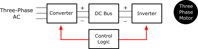
In essence, for a VFD to adjust the input frequency and voltage to an AC induction motor, it takes in AC input from the main supply line. Next, the rectifier unit (AC to DC converter) converts the fixed frequency, fixed voltage AC input to fixed DC voltage. The resulting DC output is unsteady and is sent out to an intermediate DC Bus where it’s filtered and smoothed by capacitor filters.
The filtered DC voltage then flows into the Inverter unit where it’s converted to variable frequency AC voltage through the switching operations of the power transistors inside the inverter. Next, the inverter output (variable frequency AC voltage) is delivered to the target AC induction motor at the required frequency. By adjusting the parameter settings of the VFD through the control unit, the RPM speed of the connected motor can be regulated accordingly.
Why are Brake Units Necessary in Some VFDs?
Braking circuits in VFDs are essential to the proper operation of electro-mechanical systems that employ VFD-equipped AC induction motor units controlling high inertia loads. In such applications (i.e.in centrifuges, elevators, and cranes), the VFD is subjected to potentially huge amounts of regenerated energy from the AC induction motor. This can damage the VFD hardware or cause nuisance VFD faults. How does regenerated electric energy come about?
In VFD-based speed control systems, the basic way to decelerate the RPM speed of a target AC motor is to decrease its input frequency. But when high inertia/heavy mechanical loads are involved, the rate of decrease of the motor speed can’t keep up with the motor’s synchronous speed. During this period, the cutting rotation of the rotor windings is in the opposite direction of the motor’s running speed. And whenever the rotor frequency of an AC induction motor is more than the stator frequency, the induction AC motor automatically turns into an induction generator. When this happens, current will start flowing from the AC induction motor (now an induction generator) towards the mains power line rather than from the mains to the VFD-controlled motor.
However, in general, Variable Frequency Drives controlling AC induction motors are not designed to return electrical energy from the AC motor back to the main supply. This is because these VFDs usually have either a three-phase, full-wave SCR bridge or a three-phase, full-wave diode rectifier as the means of converting the three-phase input AC supply to fixed DC voltage that is smoothened and stored in the DC Bus Link capacitors. The devices making up the input bridge rectifier (either diode or SCR type) are designed to only allow supply power in and block any current flow from the motor (when it is regenerating) towards the mains; so the regenerated current can only flow into the DC Bus capacitors. Thus, the voltage generated by the AC motor will add to the voltage already present on the DC Bus capacitors.
Whenever this happens the voltage across the DC Bus capacitors rises and if left uncontrolled it can exceed the capacitors’ maximum voltage rating. This would cause the capacitors to overheat due to electrical overstress, ultimately causing a VFD failure. To prevent this from happening, some VFDs, particularly those controlling motor systems driving high-inertia mechanical loads, include an intermediate braking circuit (brake unit) to dissipate the excess voltage generated by the motor.
Functions of Brake Units in VFDs
Brake units are introduced into a VFD-based motor control system in order to prevent damage to the VFD’s hardware components and/or nuisance system faults. They are necessary for operations where the VFD-controlled AC motor is acting as an induction generator and electrical power is flowing towards the mains supply line, rather than towards the connected motor. As previously stated, an AC induction motor will act as an induction generator whenever there is an overhauling load (i.e. when the motor is being used to maintain a steady speed of an elevator moving down while gravitational forces try to accelerate it) or when the Variable Frequency Drive is being used to decelerate the motor.
In such cases, the Counter Electromotive Force (CEMF) created by the running AC induction motor increases during overhauling or deceleration, essentially turning the AC motor into an electric generator. The amount of CEMF voltage generated by the AC motor (now a generator) is determined by the rate of overhauling/deceleration and the size of the connected high-inertia load.
There are several basic ways to deal with the energy generated by the induction motor when acting as an induction generator. First, the VFD circuit can include a DC Bus whose capacitors have the capacitance to absorb a considerable amount of the regenerated electric energy for a short period of time without overheating. However, this method is only efficient in cases where overhauling loads are not present and when the VFD-controlled motor does not require fast deceleration. If there are segments of the duty cycle of the VFD-equipped motor system where the energy generated by the motor is more than the VFD circuit can handle alone, then a brake unit (i.e. a braking resistor) can be introduced.
If the braking circuit used involves a braking resistor, it will dissipate the regenerated voltage by converting it to heat energy across the resistor element. Various types of VFD braking circuits function in different ways (as we’ll discuss in the next section), but their role is to dissipate the regenerated electrical energy from the VFD-controlled AC motor to protect the VFD hardware components from damage and to also avoid nuisance system faults.
Types of Braking Methods in VFDs
Dynamic Braking
A dynamic braking system is an integral part of sophisticated VFDs controlling large AC induction motors used to lift heavy mechanical loads. This braking method is applied in motor stoppage because, during the deceleration process of the AC induction motor, its operational mode changes from motoring (electric power flowing from the VFD to the target motor) to re-generating (electric power flowing from the AC motor to the VFD). As a result, a very high amount of voltage is generated by the motor. This is when the excess electrical energy generated by the decelerating motor is dissipated as heat energy through a voltage-regulated transistor and braking resistor; thereby protecting the electronic circuit of the VFD.
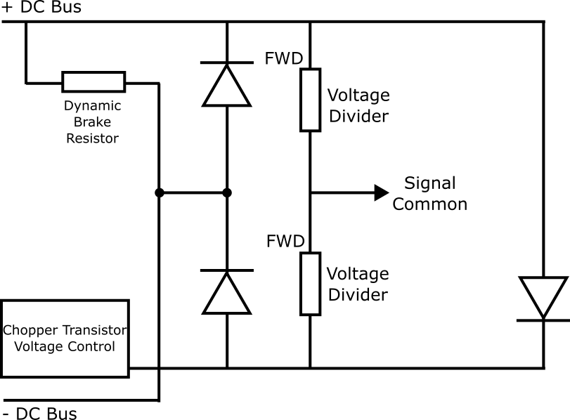
There are two versions of dynamic braking circuits that can be used with VFDs, namely: (i) A dynamic brake; (ii) A chopper. The dynamic brake circuit consists of a switching device (like an Insulated-Gate Bipolar Transistor (IGBT)), a control circuit, and a braking resistor. A braking resistor is an electrical device that makes use of voltage and dissipates power in form of heat.
On the other hand, the chopper circuit includes only a switching device and the control circuit, while the braking resistors are separate components. This allows for appropriate sizing and remote mounting of the braking resistors, given that they generate a significant amount of heat. The combination of the control circuit and a switching device (i.e. an IGBT) is commonly known as the “Chopper Module”, while the braking resistor is generally called a “Dynamic Brake Resistor.”
Dynamic brakes are conventionally rated for duty cycles in the 20% range while Chopper circuits are often employed in heavier-duty motor applications. Overall, dynamic braking is a good method for providing controlled braking in VFD-equipped AC motor units used in heavy-duty elevators, cranes, etc. However, it increases the complexity of the VFD system with additional components including the chopper module, dynamic brake resistor, and a braking control circuit.
Flux Braking
Flux braking can only be implemented in AC Variable Frequency Drives using direct-torque control (DTC) scheme. This motor control scheme decouples the torque-producing current and the flux-producing current to the target motor and controls them independently. Flux braking controls motor stoppage by taking advantage of the DTC’s separation of torque-producing and flux-producing current.
When the VFD-controlled AC motor starts acting as an induction generator–during overhauling (overrunning) or stopping– the flux braking circuit increases the flux-producing current in the AC motor. Thus, instead of sending the excess energy generated by the motor (when acting as a generator) to external resistors (i.e. Dynamic Brake Resistors), as dynamic braking does, flux braking essentially uses the VFD-controlled AC motor as the braking resistor. By increasing the magnetic flux (and, thus, the stator current) in the AC induction motor, the driven load can be decelerated quickly while the motor speed and rate of ramping down remain controlled.
With flux braking, the VFD-controlled AC motor is prone to overheating due to increased magnetic flux. Hence, this braking method is well-suited for VFD applications that only require occasional motor braking operations. If the application requires continuous motor braking or if it experiences frequent overhauling conditions, other braking methods, like regenerative braking, may be ideal.
Line Regenerative Braking
With Line Regenerative Braking, the VFD circuit takes the electrical energy generated by the connected AC induction motor and feeds it back to the mains power line (or to a common bus that supplies it to other VFDs). So, similar to Dynamic Braking and Flux Braking, Regenerative Braking also eliminates the excess electrical energy from the VFD-controlled AC motor (when acting as a generator), but instead of wasting it as heat energy in a braking resistor or into the motor flux, it recaptures it back to the power source to be used elsewhere. This still protects the VFD from nuisance faults and hardware damage.
Regenerative braking requires an AC VFD whose rectifier section is capable of allowing the electric current generated by the connected AC induction motor (when acting as a generator) to flow back to the AC power grid; in this case, the rectifier unit functions as the absorber of the regenerate current. An example of a VFD type that’s suitable for Line Regenerative Braking is the “Active Front End” (AFE) VFD topology. Instead of having just a simple passive diode bridge rectifier, this type of VFD incorporates another set of active power transistors on the front–end of the rectifier section, known as “Line Inverter”–which is different from the “Load Inverter” on the output end of the VFD. This Line Inverter takes the regenerated electrical energy off the connected AC motor and pumps it back into the main power supply line to be used by other AC loads in the system
Regenerative braking can also be made possible using a REGEN unit, if the system’s duty cycle is too high or if the regenerated energy from the motor is continuous. This allows the Variable Frequency Drive to handle electric power flow in both directions–to and from the connected AC motor.
Since regenerative braking does not increase heat in the VFD-controlled AC motor, it is best suited for VFD applications that require frequent motor stops, constant deceleration, or those handling overhauling loads. The downside of this braking method is that it’s typically a more costly alternative because specialized regenerative VFDs (those using two inverters back-to-back) are significantly more expensive than standard, non-regenerative VFDs. But energy recovery savings obtained with line regenerative braking can negate some of the capital costs of the VFD hardware.
DC Injection Braking
This method involves injecting DC voltage (sourced by the VFD’s DC bus) into the windings of the connected AC motor. As a result, the magnetic field in the motor will become fixed instead of rotating. Motor braking happens as the rotor tries to align to the stationary magnetic field. Thus, like Flux Braking, when DC Injection Braking is applied, the energy generated during motor stoppage is dissipated by the VFD-controlled motor as heat. Note, that before the onset of DC injection braking, the AC voltage is supplied to the motor through the VFD must first be disconnected to allow DC voltage to be applied to the motor.
DC injection braking is a quick, efficient, and effective method of rapidly decelerating a high-inertia load being controlled by a VFD-equipped motor unit. It’s a standard feature on most of today’s VFDs since it’s easy to implement as external components are not necessary. However, because there’s no control of the increased rate of the motor flux, DC injection braking can only provide uncontrolled motor braking.
DO Supply Inc. makes no representations as to the completeness, validity, correctness, suitability, or accuracy of any information on this website and will not be liable for any delays, omissions, or errors in this information or any losses, injuries, or damages arising from its display or use. All the information on this website is provided on an "as-is" basis. It is the reader's responsibility to verify their own facts.