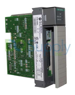
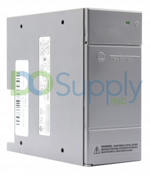
SLC 500 Power Supplies
Overview of SLC 500 Modular Control System
A modular control system comprises a power supply, CPU, input/output modules, and an operator interface device. Modular controllers contain up to three input/output modules, including programmable logic controllers (PLCs), distributed I/O systems, actuators, or sensors, each used in various combinations depending on their intended purpose.
Environment and Enclosure
SLC 500 Power Supply is made for Pollution Level 2 Industrial use in situations that have overvoltage Category II levels (as defined in IEC publication 60664-1). Up to 2,000 meters (6,561 feet), this equipment can still be classified as an industrial-grade Class A, Group 1 machine. This means that although there are occasional issues with EMC(electromagnetic compatibility) when using it in other environments, these complications can easily be avoided when the right precautions are taken. It is also supplied as an open type device. Anyhow, the user must use it with proper housing according to its environment.
Hazardous Location Considerations
Each product is labeled with the hazardous location temperature code required for use, ensuring that one would not go beyond the least temperature mentioned for any part. Please note that combinations of equipment within the system may need to be approved by the local authorities. If a hazardous situation occurs, the machine owner must follow these warnings carefully:
• Not to disconnect anything from the electrical supply until all voltage sources have been turned off and it is confirmed safe to do so.
• Not to disconnect connections associated with this device when power sources are still active or when the area has not yet been assessed as safe – to secure these connections with tools supplied with each device by the supplier.
• Even if all other provisions seem compatible, substituting any part of this device will make it unsuitable for Class I, Division 2 areas/buildings, or higher hazard classifications. Be sure to follow every instruction when installing wire connectors too!
Selecting SLC 500 Power Supply
To choose a power supply, you need:
• Specifications of the power supply.
• A worksheet for your chosen model of power supply.
• Publication 1747-SG001: SLC 500 Systems Selection Guide.
Modular systems require one power supply per chassis to make the system function properly; otherwise, there could be a risk of overloading the used power supply leading to shut down or premature failure.
For example, there are three types of AC Power Supplies and four types of DC Power Supplies from which to choose. One huge consideration is whether it comes with both 120v and 240v input voltage – this is determined by either using an internal jumper on the unit itself or using two external cables.
Use of Isolation transformer
If an environment experiences frequent electromagnetic interference in or near any distribution equipment, it is suggested to use an isolation transformer on the AC line to the power supply. Generically, an isolation transformer is typically used when voltage step-down is needed. However, it also isolates the circuit from the power system fluctuations or serves to isolate the system. When using any transformer with a controller, ensure it has enough amperage for its load, usually measured in volts-amperes (VA).
To select an appropriate isolation transformer:
- Calculate the power requirements for every circuit and load connected to this transformer.
- For inputs – determine how many input pins are attached, what voltage they need to operate at, and how much current they’ll draw when running.
- For outputs – calculate output pins, voltage, and current at the load side.
Input Voltage Characteristics
For an input voltage to be considered acceptable, it must be between 85-132 volts AC RMS (170-265 volts AC RMS in 240-volt mode). The frequency of the applied voltage must be between 47 to 63 Hz. Each cycle needs to have symmetry and follow this requirement.
Operating Range of Power Supply
Systems can operate for a set amount of time when there is an interruption in power before shutting down. This amount of time varies depending on the factors involved; for example, input modules’ number, type, and states. A typical program scan holdup time after the loss of power ranging from 20ms to 3s, usually dependent upon which I/O modules are being used. Once this length has been reached, there is an automatic shutdown initiated by the power supply module, which turns off all status lights at once. Up to 300ms of power outage triggers a remote power fail error in multi-chassis systems. To fix this issue, turn off the system or use a programming device to initiate a reboot process.
Power Down Input States
The power supply Hold-Up Time (meaning 20 milliseconds to 3 seconds) is longer than either turn-on or turn-off times for input modules. Therefore, an Input Module going from ON to OFF may cause a record of its status change before a Power Supply failure can turn it off. Understanding this is key. When writing the User Program, you must ensure that an input module always stays on. For example, connect one spare input permanently and monitor whether or not it stays ON in the programming code before moving on to other steps if no inputs are left ON.
24V DC User-Power Overcurrent Condition
For models of 1746-P1, made in Japan, if the power supply shuts down or there is a CPU fault, restarting the user program is suggested. Models of 1746-P2 series A (A, B) and 1746-P4 series A should restart the user program after shutting down or experiencing faults while operating with a power supply. Models of 1746-P1 series A made in Malaysia, 1746-P2 series C, 1746-P5 series A, and 1746-P6 series A would have correct overcurrent condition when user shutdown occurs that of 24V DC while CPU continues. Models of 1746-P1 made in Malaysia, 1746-P2 series C, 1746-P5 series A, and 1746-P6 series A power supplies also need to monitor outputs of 24V DC at all times due to unexpected operation arising from user shutdown.
Undervoltage Operation
It is possible for an SLC 500 controller to remain operational at reduced levels of power – but only for a certain duration before shutting down. If the input voltage to an SLC 500 controller falls below its recommended operating range, it will cease operation and resume once the correct level has been reached. However, suppose the input voltage to a 1746-P7 power supply falls below its 4-9 volt range and remains low temporarily. In that case, the Controller will shut down entirely and stay that way until corrected.
General Specifications (1746-P1, 1746-P2, 1746-P3, 1746-P4, 1746-P5, 1746-P6, and 1746-P7)
Model 1746-P1 SLC 500 Power Supply: It has a line voltage of 85-132/170-265V AC with 47-63 Hz frequency. The typical line power requirement is 135VA with an initial surge of up to 20 amps. It offers an internal current capacity of 2 Amps (at 5 Volts DC) and 0.46 Amps (at 24 Volts DC). For the user, it can supply up to 200 milliamps on the 24 volts, which supports both 18 – 30 V DC voltages while also protecting against overcurrents if they’re caused by either 15 A or less than 15A. Current capacity is reduced by 5% over 55 °F (131 °F), depending on full or no load conditions. This type of power supply can isolate 1800V AC RMS for 1 second with a CPU holdup time of 20 ms (full load) and 3000 ms (no load).
Model 1746-P2 SLC 500 Power Supply: It is made to use 85-132/170-265V AC with 47-63 Hz of frequency. The specific power needs are 180VA, and inrush currents are up to 20A. The internal current capacity is 5 A (at 5 V dc) and 0.96 A (at 24 V dc). It has a rated current capacity of only 200 mA @24 VDC and an 18 – 30VDC voltage capacity. With a temperature range from 0-60°C, the current capacity only exceeds 5% over 55 degrees Celsius (131 Fahrenheit), with a CPU holdup time of 20 milliseconds at full and 300 milliseconds at no load.
Model 1746-P3 SLC 500 Power Supply: It features 19.2-28.8 V dc line voltage. Typical line power requirements are 90VA with an inrush current of up to 20A. Internal current capacity is 3.6 A @ 5V dc and 0.87 A @ 24VDC. Ambient operating temperatures range from 0-60°C when derated by 5% over 55 °C (131 °F). This type of power supply can isolate 600 volts ac RMS for 1 second without failing down when holding up computer data transfer rates for 5ms at full load and 1000ms at no load.
Model 1746-P4 SLC 500 Power Supply: It has an input voltage of 85-132/170-250V AC with a frequency of 47-63 Hz. It typically consumes 150VA and provides inrush current up to 45A. Its internal capacity is 10.0 A @ 5V dc, 2.88 A @ 24V dc. Overcurrent protection for this type of power supply is 15A and the operating temperature range is between 0 to 60 degrees Celsius. This type of power supply can isolate 2600V dc for 1 second with a CPU holdup time of 20 ms (full load) and 3000 ms (no load).
Model 1746-P5 SLC 500 Power Supply: It is rated at 90 – 146 V DC. It needs 75 VA of power with an inrush current of up to 20A. Its maximum internal current capacity is 5 A (at 5 VDC) or 0.96 A (at 24VDC). The maximum input current capability for the 24 V DC mode is 200 mA, with a voltage capacity of 18 – 30 VDC. This type of power supply can isolate 1800V ac RMS for 1 second with a CPU holdup time of 20 ms (full load) and 3000 ms (no load).
Model 1746-P6 SLC 500 Power Supply: It has a voltage range between 30-60 Volts. The typical line power requirement is 100 VAs, with an inrush current range of up to 20 Amps. This supply has an internal capacity of 5 Amps (at 5 Volts) and 0.96 Amps (at 24 Volts). 24 Volt user-power capability includes 200 mA and voltage capacity limited to 18-30 Volts. Ambient operating temperatures range from 0 degrees Celsius to 60 degrees Celsius. If the ambient temperature exceeds 55°C or 131°F, capacity is reduced by 5%. This type of power supply can isolate 1800V ac RMS for 1 second and comes with a CPU holdup time of 5 milliseconds (full load) and 1500 milliseconds (no load).
Model 1746-P7 SLC 500 Power Supply: It has an input voltage range of 10-30 VDC and a typical power output of 50 VA @ 12V and 75VA @ 24V. Operating at 12 VDC consumes two amps while drawing 5 volts or 0.46 amps while drawing 24 volts. Operating at 24 VDC consumes 3.6 amps while drawing 5 volts or 0.87 amps while drawing 24 volts. The ambient operating temperature ranges between 0° C to 60°C (32° F) with a derated performance of 5% when the temperature reaches 55 °C (131 °F). It can sustain up to 600Vac for 1 second during normal operation and includes CPU Hold Up Time settings for 12 VDC (1.37ms @ 0v dc [fully loaded], 895 ms @0v dc [no load], 10ms @9v dc [fully loaded and continuous operation]), and 24 VDC inputs (40ms @ 0v dc [fully loaded], 1860 ms @0v dc [no load], 790ms @11v dc [fully loaded and continuous operation]).
Sinking and Sourcing Points for I/P Modules
Sinking and sourcing are two terms that describe how a signal flows through devices in a control system. Devices connected to the field power supply’s positive side (+V) provide energy and are known as sourcing; those connected to the negative side (common ground, dc common) receive it instead and are known as sinking.
This definition is expanded to cover input/output modules on discrete I/O boards to maintain compatibility within these systems. I/O module inputs provide an electric source for other circuit outputs; circuitry outputs provide an electric sink for I/O module inputs.
Solid-State DC I/O Circuits
It is typical for dc field devices to be used in a specific sourcing or sinking circuit based on its internal circuitry. Input and output circuits are commonly used with these devices requiring a predetermined voltage – either direct current (dc) or alternating current (ac).
- Source Device with a sinking input module circuit: in this case, the field device lies on the positive side of the power supply between the supply and the input terminal. The module will source current to the input circuit when activated.
- Sinking device with sourcing input module circuit: here field device remains on the negative side of the power supply, which connects to the input terminal. If activated, it will sink current from this input circuit.
- Sinking Device with Sourcing Output Module Circuit: The sink module has sourcing capabilities when the output is activated. It can provide power to the field device on the negative side of the power source, between the source and outbound terminals.
- Sourcing Device with Sinking Output Module Circuit: here field device is on the positive side of the power supply between the supply and the output terminal. When activated, it sinks current from the field device.
Powering the Link Coupler with a Power Supply
In Normal Operation, the Controller will power the Link Coupler and any connected peripheral devices. To connect the processor to the link coupler, both need to be connected via a 1747-C11 cable. However, if no connection is made between the two devices – a 24VDC power supply needs to be used instead for them to work properly. The 1747-AIC interface requires 85 milliamps of current at 24 volts of dc when no peripherals are attached or 190 milliamps with peripherals.
DO Supply Inc. makes no representations as to the completeness, validity, correctness, suitability, or accuracy of any information on this website and will not be liable for any delays, omissions, or errors in this information or any losses, injuries, or damages arising from its display or use. All the information on this website is provided on an "as-is" basis. It is the reader's responsibility to verify their own facts.