Understanding PLC Communication: How Controllers, HMIs, and Drives Stay in Sync
In the architecture of modern industrial automation, the common thread that ties everything together is synchronization. This ensures everything operates in real time. The regular and consistent exchange of data among the main control elements, namely Programmable Logic Controllers (PLCs), Human-Machine Interfaces (HMIs), and motor drives, is the nervous system of any automation system. The communication efficiency of the manufacturing, energy, and transport systems determines their impact on intelligence, safety, and efficiency. This article explains the technical nature of this interaction by examining the role of each device, the language they speak, and the physical and logical paths that must be in place for it to work properly.
The Centralized Brain and the Interactive Window
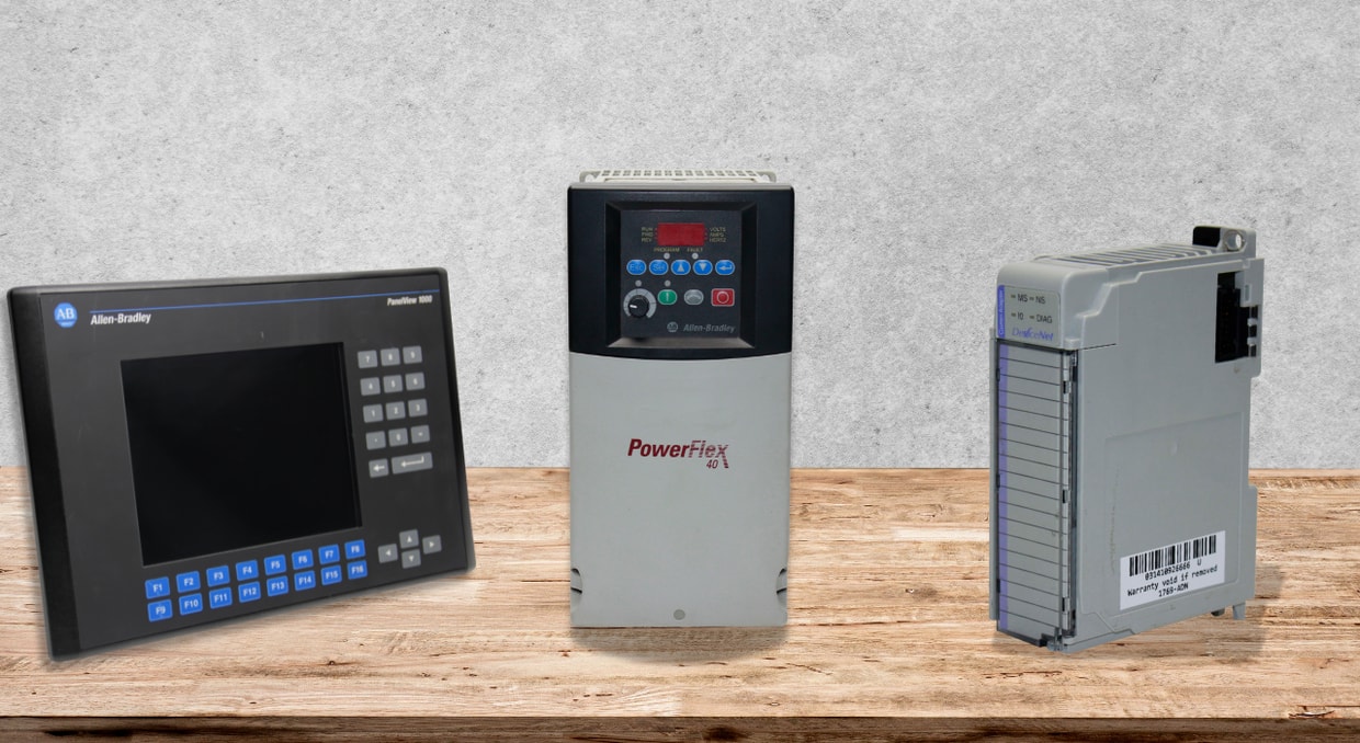
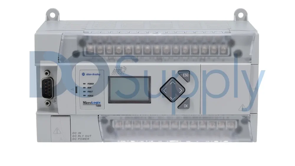
At the center of any control system is the PLC, which is undoubtedly the brain of the operation. These are computer systems that are designed for industrial use. The main task of these devices is to run logic control and deterministic logic control. The devices perform this by scanning continuously. The inputs in this case are measured values from sensors and devices. A user-written program processes this data. The second data is output to actuators, valves, and most importantly, drives. With these outputs, a motor drive can be switched on and off, or its speed can be precisely increased or decreased. They are thus capable of automating a physical process directly. The PLCs can effectively repeat the control cycle at high speed. Hence, a PLC can make a group of machines work as a single automated system.
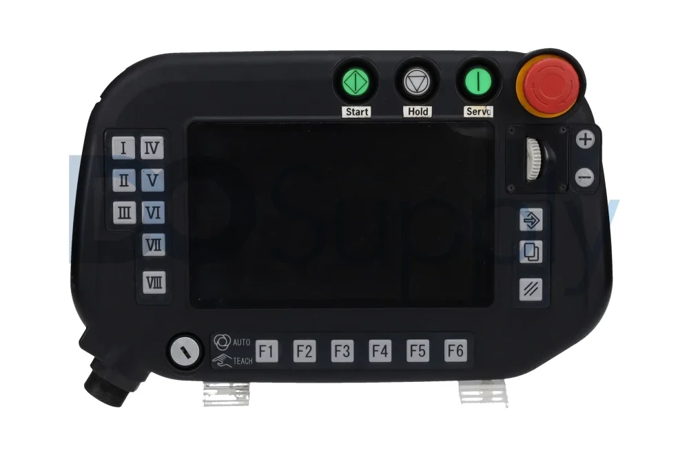
Furthermore, the HMI is the missing link that connects human operators with the machine-level logic of the PLCs. The HMI provides a visual, interactive interface for the user, allowing them to see the process, most commonly via a dedicated touchscreen or a computer monitor. It converts raw data and status bits from the PLCs into user-friendly graphical representations—it can indicate process flow, display real-time values, and even show alarm states. At the same time, it sends operator commands, such as starting a machine sequence or setting a new parameter, to the PLC that controls the process. Monitoring and supervisory control become possible with such a bidirectional flow, making the whole system accessible and manageable.
It is such a powerful synergy when the two technologies, that is, PLCs and HMIs, are put together. Quite often, a single PLC can supply data to numerous HMIs, thus allowing different operator stations or roles to have a view of the same process at the same time. On the other hand, a single HMI can be set up to talk with many PLCs, thus becoming a centralized command center for a whole line or a cell consisting of several controllers. Through the networked method, the control system is made visible, which not only facilitates decision-making but also makes it easier to derive critical information from several PLCs in a unified graphical format. Consequently, operational efficiency is greatly elevated as personnel can act upon the conditions in a flexible manner when they have a complete and up-to-date overview of the situation.
The Three Pillars of Synchronization: Physical, Protocol, and Configuration
There is a structured approach involved in setting up and maintaining a sync between PLCs, HMIs, and drives, which involves three different but integrated components: physical connection, communication protocol, and software.
The Physical Bridge: Wired and Wireless Pathways
Step 1 involves establishing a tangible connection. Both PLCs and HMIs are equipped with communication ports that support different communication standards. Some of the popular wired interfaces are Ethernet, which provides a high-speed data network, and serial interfaces such as RS-232, which provides a point-to-point interface, and RS-485, which provides a multi-drop interface. In certain instances, a wireless data transmission interface, such as Wi-Fi and/or cellular interfaces, can also be used. However, network security, as well as the extent of potential interference, becomes a factor in using a wireless connection for data transmission, which needs to play a significant role in keeping it secure and reliable, as in a PLC.
The Common Language: Communication Protocals
A protocol is not negotiable when it comes to data. These are rules that govern how data is formatted, how data needs to be addressed, how data needs to be sent, and how data needs to be received. When a PLC wants to command a drive to speed up, for example, it has to communicate through a protocol. There are a number of major ones in the industrial world:
- Modbus, in both RTU (serial) and TCP (Ethernet) form, has a reputation for being extremely simple and popular.
- EtherNet/IP and Profinet are high-speed, deterministic networks that use standard Ethernet cabling for transporting real-time control data.
- It has a modern, platform-independent architecture that focuses on secure data exchange and information modeling.
- Vendor-specific protocols such as S7 Communication of Siemens, MELSEC of Mitsubishi, and FINS of Omron are also popular in their own right, which are optimized for their own environment. The drives and other peripheries should also support the protocol network used in the master PLCs.
The Logical Mapping: Network and Data Configuration
With hardware in place and a protocol defined, careful configuration integrates hardware in a logical manner. This requires assigning a distinct network address, such as an IP address used in the Ethernet protocol, to every hardware component, including every PLC and drive, in order to effectively direct communication. In programming software used for HMI and PLC, data tags or variables are established. A graphical button on an HMI screen, for example, corresponds with a particular control bit in PLCs, which corresponds with a drive output. This configuration guarantees that a human operator’s input corresponds in a direct manner with a physical event. Additionally, network parameters, including sub masks and gateways, must all be consistent, along with any software firewalls for allowing communication traffic.
Bridging Interface and Protocol Gaps
In practice, achieving this often requires additional hardware to bridge compatibility gaps. Many legacy PLCs rely on serial communication, which does not directly integrate with modern Ethernet-based HMI networks. This limitation can be addressed using serial communication converters, such as RS-232 to RS-485, along with a serial device server.
A serial device server connects directly to the PLC’s serial port and converts the data stream into Ethernet traffic. From the HMI’s perspective, the PLC appears to be a native Ethernet device, allowing it to communicate over a standard network. This approach makes it possible to integrate older PLC hardware into centralized monitoring systems without replacing existing equipment, preserving prior investments while modernizing system visibility.
Key Protocols Enabling Sync
Historically, knowledge about the features of prominent protocols is vital for developing a coordinated system. Modbus, a master/slave protocol, has been a popular choice due to its simplicity. Modbus operates as follows: a master, which in many cases will be an HMI or a master PLC, polls slaves, which in this case will be PLCs, drives, and/or sensors. The simplicity of Modbus has led to it being used as a popular protocol for connecting various devices together. Profinet and EtherNet/IP are types of industrial Ethernet. They use standard Ethernet cables and switches, but also provide additional features for real-time processing. These networks are able to provide high speed with guaranteed, synchronized timing.
Examples of programming using these networks would be in a high-speed packaging operation that involves coordinating a number of motor drives. Communication in these networks can also involve larger amounts of data. OPC-UA has become steadily more important for secure data integration. OPC-UA has evolved from a mere data access platform to a model for describing complex data, including historical data, in a standardized form. OPC-UA contains inherent security capabilities. These capabilities are important from a cybersecurity point of view. OPC-UA usually works in conjunction with other data access specifications, connecting data exchange between PLCs, HMIs, and other systems like MES and cloud-based systems in a secure and standardized manner.
The Configuration Workflow
There is a systematic process involved in implementing communication. The Hardware Setup involves installing all PLCs, HMI modules, drives, and network components.
Then, there comes the step of Parameter Configuration, which requires the application of engineering software tools to enter the communication parameters of every device. This involves assigning the IP addresses, protocol detail programming, including Modbus Station Number and Ethernet/IP Network Name, as well as matching baud rates.
This is where logical connections are established. In PLC programming, data blocks or registers are allocated for data exchange. In the HMI development software, graphical objects are prepared, and their tags are directly allocated to specific memory addresses in the PLC. Parameters are then allocated to establish control words and feedback registers that can be accessed through the network for drives.
Finally, a thorough Testing and validation take place. The engineers are involved in communication diagnostics, analysis of force values in the PLC for updates in the HMI, as well as commands from the HMI to check control of PLCs and drives. This ensures that the synchronization loop is closed, reliable, and functions as expected.
Conclusion
A PLC, HMI, and drive working in concert involve a constant and choreographed dialogue. This dialog begins with a solid hardware infrastructure, a common description for this dialog, and a precise match of software. Beginning with a constant scan, which occurs in a PLC, to a graphical representation in an HMI, which closely follows a precise plan of motion from a drive, all are different. A deep understanding of how these different components communicate, this dialog, how they are integrated, in essence, how they are in sync, becomes a requisite for a proficient design, implementation, and operation of efficient, effective, and intelligent automation systems, which sustain a growing industry. The continuous advancement of this dialog in terms of speed, security, and compatibility, as found in OPC-UA, envisions a bright and enhanced dialog in upcoming industries.
We at DO Supply carry drives, PLCs, HMIs, and more, all ready to be installed together to create a harmonious system ready to take the world by storm. We have products from brands like Allen-Bradley, Siemens, OMRON, Mitsubishi, and more. Not only that, but all products ship out same day and with a two-year warranty. We also have our team on standby to help if you need recommendations on products, compatibility, and availability. Give us a call today to see what we can DO for you.
DO Supply Inc. makes no representations as to the completeness, validity, correctness, suitability, or accuracy of any information on this website and will not be liable for any delays, omissions, or errors in this information or any losses, injuries, or damages arising from its display or use. All the information on this website is provided on an "as-is" basis. It is the reader's responsibility to verify their own facts.