Analog Input vs Digital Input: The Electrical Science Behind Automation Controls
Analog and digital inputs are the primary mechanisms by which automation systems interpret and sense the physical world. Each industrial automation system relies on input signals to measure process variables, monitor states, and provide feedback to the connected controller. Originating from field input devices such as transmitters, switches, pushbuttons, and sensors, these signals are transmitted to input modules and serve as the foundation for all subsequent decision-making and control logic. Input modules in automation systems are engineered to reliably convert electrical signals into usable data while maintaining high accuracy, effective electrical isolation, and immunity to noise.
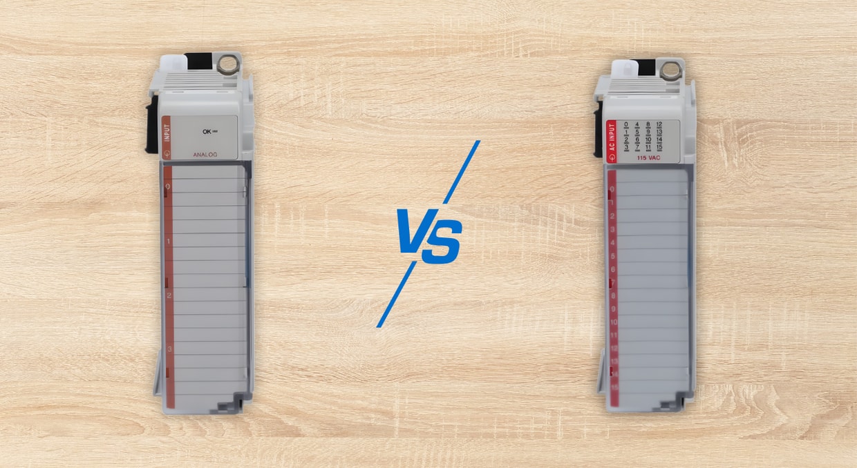
The key distinction between digital and analog inputs lies in how information is represented: digital inputs communicate information in discrete, non-continuous steps, typically representing binary states such as ON/OFF or True/False, while analog inputs utilize continuously varying measurements to represent a range of values. Understanding this key difference is essential for technicians and engineers who are responsible for designing, building, commissioning, troubleshooting, and maintaining dependable automation systems.
Understanding Analog vs Digital Inputs in Industrial Control Systems
In Industrial control systems (ICS), an input is an electrical signal sent from a field device to a controller for analysis and processing. These inputs enable controllers to monitor operator commands, process variables, and machine status for automation control. In analog vs. digital input systems, the input type determines how the controller processes, acts upon, and stores information. Within the controller’s input image table, digital inputs are stored as individual memory bits, whereas analog inputs are stored as data words containing scaled numerical values.
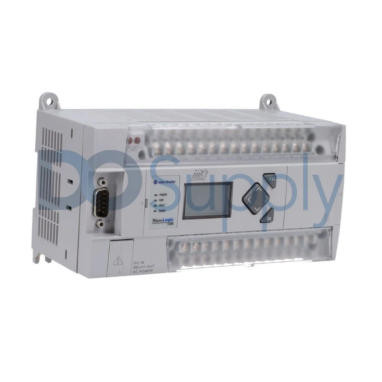
A typical example of an Industrial Control System is a Programmable Logic Controller (PLC). In PLCs, the input scan cycle is a continuous operation in which the controller collects data from analog and/or digital field input devices, executes programmed logic, and updates the connected outputs accordingly. Analog inputs provide continuous feedback, such as a range of pressure and temperature values, whereas digital inputs report event-based, discrete information, for instance, if a field device is energized or not. It is worth noting that PLCs are digital processors, and as such, their analog input signals must be converted to digital signals using Analog-to-Digital (A/D) modules.
Industrial control systems deal with both varying process values and discrete events, all of which provide essential input signals. Understanding the distinction between analog vs digital inputs ensures that industrial control systems are electrically sound, precise, and responsive. Digital input signals are simple, easier for ICS to process, and less prone to electrical noise, but they cannot measure gradual changes. On the other hand, analog input signals provide detailed input data, enabling precise automation control. They are, however, more complex, highly susceptible to electrical noise, and they often require conversion to digital form for processing.
Digital Inputs: Definition and Operating Principle
A digital input is an electrical signal that can be in one of two possible states, commonly described as ON or OFF, much like a light switch. In the analog input vs digital input context, digital inputs are often referred to as discrete inputs since they represent distinct conditions with no intermediate values.
In industrial automation applications, discrete input modules usually operate at standard voltages such as 24 VDC, 230 VAC, and 120 VAC. Such modules are used to interface field devices like proximity sensors, push buttons, and limit switches with digital industrial controllers – PACs, SCADA systems, PLCs, etc. The specific operating voltage of a digital/discrete input module is determined by the voltage/current provided by the connected field device, the controller’s logic-level requirements, and the need to ensure signal integrity over varying distances.
Electrically, a digital input operates by detecting whether the applied voltage is above a specified threshold. When the voltage exceeds this level, the input is interpreted as ON; otherwise, it is considered OFF. Some digital input modules incorporate opto-isolators that provide electrical isolation between the controller’s internal logic and the field wiring. This protects the internal circuitry from electrical noise and transient voltages.
Digital inputs are more robust because they rely on simple threshold detection rather than the precise voltage-measurement techniques used by analog inputs. This inherent design difference makes digital inputs more resistant to electrical noise and interference, and thus, a great choice for electrically noisy industrial settings. Due to their high reliability and deterministic nature, digital inputs are also ideal for implementing robust control, interlocking, and safety-related functions in industrial automation.
Analog Inputs: Definition and Signal Conversion
An analog input is an electrical signal that varies continuously within a specified range of operating values, representing the magnitude of physical process variables like flow rate, pressure, or temperature. In analog input vs digital input systems, analog inputs are critical when trend analysis, proportional-integral-derivative (PID) control, and high-resolution measurements are required.
Common industry-standard analog input signals include 0-10V and 4-20 mA; both are prevalent due to their compatibility with a variety of industrial transmitters and sensors. They also offer specific technical advantages for various industrial automation applications, for example, the 4-20 mA signal provides robust signal integrity over long distances, while the 0-10 V is renowned for its wiring simplicity, application flexibility (high- or low-speed), and lower cost.
In contrast to discrete digital inputs, continuous analog inputs require analog-to-digital conversion before digital processing. An Analog-to-Digital Converter (ADC) captures incoming analog signals, quantizes them into discrete numerical values, and records the results in the controller’s data table. The conversion process involves:
- Sampling: The ADC measures the amplitude of the continuous analog input signal in periodic intervals at a specific sampling rate. Based on the Nyquist theorem, this sampling rate should be at least twice the signal’s maximum frequency to prevent aliasing and ensure accurate signal reconstruction. The result of the sampling process is a series of discrete analog signals.
- Quantization: The sampled amplitude values of the analog input signal are approximated to a finite set of discrete numerical values, expressed in binary form. The ADC resolution defines how precisely the specified signal range is quantized.
- Encoding: The discrete numerical values are then converted into a unique binary code and saved as digital data within the processor’s memory or the data table of the connected controller.
The Electrical Science Behind Automation Controls
- Signal Representation: In industrial automation, analog and digital inputs are fundamentally different in terms of electrical behavior and signal representation. Digital inputs analyze discrete signals using threshold logic, converting input voltages that fall outside the set threshold into digital ON/OFF states. They also employ hysteresis and opto-isolation for reliable, noise-resistant operation.
In contrast, analog inputs measure continuous variable signals, such as 4-20mA or 0-10V analog signals. Using a high-resolution A/D converter, the measured range of values is converted into precise digital data points, enabling fine-grained process monitoring. Because analog signals are usually more vulnerable to electrical noise, they require proper signal conditioning and adequate shielding. Overall, the choice of the appropriate type of analog input vs digital input is a balance between measurement precision, system dependability, and application requirements.
- Resolution, ENOB, and Measurement Accuracy: Resolution is a key determinant of performance in analog input vs digital input automation systems. Digital inputs operate at one-bit resolution, which is sufficient for detecting the input states (e.g., ON/OFF). Analog inputs rely on the A/D converter’s resolution, which typically ranges from 12 to 16 bits. The Effective Number of Bits (ENOB) is a more practical measure of system performance, as it quantitatively accounts for how signal imperfections like noise, distortion, and nonlinearity reduce the ideal resolution of an A/D converter. A high nominal resolution does not automatically guarantee accurate or high-precision digital/analog measurements. Instead, optimal system performance also requires adequate noise suppression, signal integrity, and reference stability.
- Current Loop Physics: The prevalence of the 4-20 mA analog signal as an industry standard in the context of analog input vs digital input systems stems from basic circuit theory. Whereby, current remains constant in a series loop, as such, variations do not influence the measured signal in cable resistance. In addition, the accuracy of a signal is not affected by any voltage drop across the wiring. Current signals are more resistant to electromagnetic interference because electrical noise is normally introduced as a voltage. The four mA ‘live zero’ feature enables detection of broken wires, making current-based analog inputs well-suited for harsh industrial environments and long-distance signal transmission.
- Common-Mode Voltage and Differential Measurement: Common-mode voltage is an important consideration inanalog input vs digital input automation controls. Differential analog inputs are designed to measure the voltage difference between two conductors, enabling them to effectively reject common-mode noise. In industrial settings, a high common-mode rejection ratio (CMRR) is vital for accurate input measurements. Since the operating principle of digital inputs is based on simple threshold detection, they are generally less sensitive to common-mode noise.In essence, differential measurement is a key element in the design of analog control systems.
- Electrical Isolation and Protection: Electricalisolation approaches differ significantly for analog input vs digital input automation systems. Digital inputs typically use optocouplers or magnetic/capacitive digital isolators to ensure high isolation-voltage ratings and reliable, noise-resistant signal transmission. On the other hand, analog inputs require electrical isolation to minimize errors such as temperature drift and to preserve linearity across a continuous spectrum of values. Sigma-delta A/D converters and isolation amplifiers are frequently employed in the front end of an analog input to achieve this.
Insufficient isolation in analog input vs digital systems does not necessarily result in an immediate, obvious malfunction; instead, it often leads to gradual degradation of the analog measurement’s accuracy and precision. This subtle decline in precision often leads to unreliable input data or critical system failures.
Common Industrial Applications of Digital Inputs
- Start and Stop Pushbuttons: Digital inputs generate discrete, operator-initiated control signals that trigger the necessary changes in process variables or machine conditions, once the PLC ladder logic or function block programs are executed.
- Emergency Stop Circuits: Most fail-safe emergency stop circuits are implemented using Normally Closed (NC) digital input channels that are connected to safety-related PLCs or safety relays. This design ensures that connected controllers can detect a loss of signal continuity (e.g., a broken wire) instantly and initiate an emergency stop. Afterward, the safety relays force the system into an established safe state in accordance with the relevant Performance Level (PL) and Safety Integrity Level (SIL) safety requirements.
- Proximity and Photoelectric Sensors: These are non-contact sensors that generate binary signals to indicate the presence or absence of objects in a fast-paced manufacturing environment. The detected physical phenomenon is converted into a suitable signal that meets the voltage and current requirements of the PLC’s digital input circuitry.
- Safety Interlocks and Guards: A safety guard is a protective physical barrier, while an interlock is typically a control device that detects the status of the guard (open or closed). They are integrated into automated systems to automatically stop or prevent industrial machines from starting until all defined safety conditions are met.
Common Industrial Applications of Analog Inputs
- Pressure Monitoring: Standard 4-20mA analog inputs are used to acquire variable sensor data from pressure transducers or transmitters. PLCs or other controllers use the collected data to monitor and regulate the fluid pressure of hydraulic and pneumatic systems.
- Temperature Measurement: Analog field input devices, such as thermocouples, RTDs (Resistance Temperature Detectors), and thermistors, convert continuous temperature variations into proportional current or voltage signals. The generated electrical signals vary smoothly with temperature changes, enabling precise, real-time monitoring of the thermal status of HVAC units, automotive systems, and industrial processes.
- Flow Measurement: Analog inputs acquire continuous current/voltage signals (0-10V DC or 4-20 mA) from flow meters. By interpreting the acquired raw signals, the analog inputs can compute essential flow parameters, such as volumetric or mass flow rates, for batching, dosing, and energy optimization.
- Speed Feedback: Analog input devices such as analog tachometers, rotational/linear speed sensors, and potentiometers generate variable current or voltage signals proportional to the measured position or speed. The produced analog signals are then read and interpreted by controllers for applications such as system synchronization and motor control.
Final Thoughts
At the end of the day, analog and digital inputs aren’t just electrical concepts, but the way you read a machines language. When inputs are selected and wires are properly installed, the automated system can actually do its job with confidence. This is also why the quality of your input hardware matters much more than people realize. A noisy analog signal, mismatched voltages, or a poorly insulated input module can quietly sabotage even the best automated system.
This is where having the right parts on hand makes life easier. Here at DO Supply, we carry quality parts from manufacturers that you can trust. Unsure which to pick? Check out our PLC manufacturers comparison guide here! Whether you’re upgrading a panel, inquiring on replacing or repairing a failed I/O card, or building a brand new control cabinet, we have you covered. Everything is tested, ready to ship same day, and backed by our two-year warranty to keep things worry free. So stop by our site or give us a call today to see what we can DO for you!
DO Supply Inc. makes no representations as to the completeness, validity, correctness, suitability, or accuracy of any information on this website and will not be liable for any delays, omissions, or errors in this information or any losses, injuries, or damages arising from its display or use. All the information on this website is provided on an "as-is" basis. It is the reader's responsibility to verify their own facts.